AUTOMATIC CONTROLS
The automatic controls used in a heating system are designed to insure its safe and efficient operation. Detailed descriptions of these controls are found in Chapter 4 (THERMOSTATS AND HUMIDISTATS); Chapter 5 (GAS AND OIL CONTROLS);
and Chapter 6 of Volume 2 (OTHER AUTOMATIC CON TROLS). Additional information can be found in the appropriate sections of Chapter 16 (BOILER AND FURNACE CONVER SIONS) and Chapter 2, Volume 2 (GAS BURNERS). This sec tion is primarily concerned with outlining the operating principles of the automatic controls used with a gas-fired furnace. These controls include:
1. Room thermostat,
2. Fan and limit controls,
3. Pilot safety valve,
4. Automatic main gas valve,
5. Gas pressure regulator.
The operation of the furnace is controlled by the room thermo stat. The thermostat senses air temperature changes in the space or spaces being heated and sends an electrical signal to open or close the automatic main gas valve. The thermostat is generally wired in series with the pilot safety valve, the automatic main gas valve, and the limit control. See Chapter 4, Volume 2 (THERMO STATS AND HUMIDISTA TS) for a detailed description.
The fan and limit control is a safety device which operates on a thermostatic principle. This combined control is designed to govern the operation of the furnace within a specified temperature range (usually 80°F to 150°F), and is located in the furnace plenum where it responds to outlet air temperatures.
One of the functions of this control is to prevent the furnace from overheating by shutting off the gas supply when the plenum air temperature exceeds the upper temperature setting (e.g. 180°F) on the control. The limit control switch (and pilot safety relay) responds to excessive plenum temperatures by closing the auto matic main gas valve and thereby shutting off the flow of gas to the burner or burner assembly.
Another function of the fan and limit control is to stop the fan when the gas burner or burner assembly has been turned off.
When the plenum air drops below the lower setting (e.g. 80°F) on the control, the fan is automatically shut off. For additional infor mation about fan and limit controls read the appropriate sections in Chapter 6, Volume 2 (OTHER AUTOMATIC CONTROLS).
The function of the automatic pilot safety valve is to shut off the main gas supply when the pilot flame goes out. There are several types of these pilot safety devices on the market, but the most commonly used ones are those which employ a thermo couple lead in conjunction with a valve switch.
The automatic main gas valve controls the flow of gas to the burner manifold (in the case of a burner assembly) or to the gas burner. It is located between the burner (or burners) and the gas pressure regulator. Chapter 6, Volume 2 (OTHER AUTOMATIC CONTROLS) contains additional information about both pilot safety and main gas valves.
The gas in the supply main is frequently subjected to pressure variations. A gas pressure regulator installed in the piping between the supply riser and the automatic main gas valves insures a con stant gas pressure in the burner manifold.
HEAT EXCHANGER
Each gas-fired furnace has a burner compartment containing the gas burner and pilot. The gas and air necessary for combustion are mixed in the venturi or mixing tube prior to ignition. This mixture is then ignited by the pilot flame as it leaves the burner. The burner flame is encased in a combustion chamber or fire box located directly below the furnace heat exchanger. The heat of the combustion process is transferred to the metal walls of the heat exchanger, and then to the air rising through it (Fig. 17).
The air flowing through a heat exchanger is subject to tempera tures which frequently approach the 700-800°F range. Because of these high temperatures, the air flow must be uniform across all sections of the heat exchanger, and must move at a sufficient rate of speed to keep these temperatures from building any higher. A low volume of air flowing across one section of the heat exchanger will result in overheating and the failure of the entire beat ex changer assembly (Fig. 18).
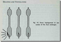
Overheating can also be caused by a portion of the gas flame impinging on the inner surface of the beat exchanger (Fig. 19).
This results in the generation of extremely high temperatures. Under normal operating conditions, the gas flame should be directed upward through the center of each section.
Another cause of heat exchanger failure is over firing. This condition is usually traced to an excessively high manifold pressure or an orifice that is too large. The result is a firing rate that exceeds the design limits.
If the heat exchanger becomes so covered with soot, carbon deposits, and other contaminants that it reduces the operating efficiency of the furnace, it should be thoroughly cleaned. Gaining access to the heat exchanger is not easy, because it requires re moving the burners and manifold assembly, vent connector, draft hood (diverter) and flue baffles. For this reason, you are advised to call a local service repairman if you want to clean the heat exchanger.
GAS BURNERS
Gas burners and gas burner assemblies are designed to provide the proper mixture of gas and air for combustion purposes. The gas burners used in residential heating installations operate pri marily on the same principle as the Bunsen burner. See Chapter 2, Volume 2 (GAS BURNERS).
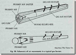
Gas-fired furnaces require both primary and secondary air for combustion process. The gas passes through the small orifice in the mixer head which is shaped to produce a straight flowing jet mov ing at high velocity (Fig. 20). As the gas stream enters the throat of the mixing tube, it tends to spread and induce air in through the opening of the adjustable shutter. This is the primary air which mixes with the gas before the air-gas mixture is forced through the burner ports (Fig. 20). The energy in the gas stream forces the mixture through the mixing tube into the burner manifold casting, from which it issues through ports where additional air must be added to the flame to complete combustion. This secondary air supply flows into the heat exchanger and around the burner. Its function is to mix with unburned gas in the heat exchanger in order to complete the combustion process.
The primary air is admitted at a ratio of about 5 parts primary air to 1 part gas for manufactured gas, and at a 10 to 1 ratio for natural gas. These ratios are generally used as theoretical values of air for purposes of complete combustion. Most burners used in gas-fired furnaces operate efficiently on 40 to 60 percent of the theoretical value. Primary air is regulated by means of an adjust able shutter. When burning natural gas, the air adjustment is generally made to secure as blue a flame as possible. Burner manu facturers provide a number of different ways to field adjust primary air. For example, shutters for primary air control are part of the main burners. Factory adjusted, angled orifices are also used on some burners.
The secondary air is drawn into the burner by natural draft. Noprovision is made by manufacturers to field adjust secondary air. Secondary air is controlled primarily by the design of the flue re strictors and draft diverter. The general configuration of the heat exchanger and burners are also important factors in secondary air control. Excess secondary air constitutes a loss and should be re duced to a proper minimum (usually not less than 25 to 35 percent).
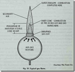
As shown in Fig. 21, a typical gas flame consists of a well defined inner cone surrounded by an outer envelope. Combustion of the primary air and gas mixture occurs along the outer surface of the inner cone. Any unburned gases combine with the secondary air and complete the combustion process in the outer envelope of the flame.
As Fig. 21 illustrates, the major portion of the inner cone consists of an unburned air-gas mixture. It is along the outer surface of the inner cone that combustion takes place. The height of the inner cone can be reduced by increasing the amount of primary air contained in the air-gas mixture. The extra oxygen increases the burning rate which causes the inner cone to decrease in size.
A burner is generally considered to be properly adjusted when the height of the inner cone is approximately 70 % of the maximum visible cone height. The gas should flow out of the burner ports fast enough so that the flame cannot travel or flash back into the burner head. The velocity must not be so high that it blows the flame away from the port(s).


