Integral-Type Gas Burners
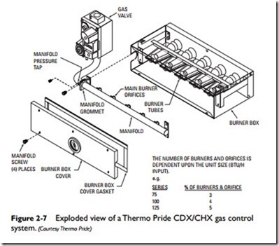
An integral-type gas burner assembly consists of an array of parallel burner tubes connected by a manifold pipe running at a right angle to them. The burner tubes and manifold are part of a box/drawer assembly in modern furnaces and boilers. The entire assembly can be removed from the furnace or boiler for cleaning (see Figure 2-7). Each burner tube contains a series of orifices (openings) through which the gas flows. These orifices are sized to deliver the required amount of gas flow to achieve the maximum ratings at the rated pressure listed on the appliance nameplate.
Note
Instructions for servicing burner orifices are included in Chapter 11 (“Gas Furnaces”) in Volume 1.
As shown in Figure 2-7, the burner manifold is connected at one end to the individual burner tubes and at its other end to the main gas valve. In other words, it functions as the bridge between the burner tubes and the main gas valve.
In many furnaces, the main burner(s) can be manually adjusted. In others, no burner adjustment is required because burner aeration has been fixed at the factory. Natural gas burner flames should be well defined (but almost transparent) and should range from light to medium blue in color. Propane burner flames often have yellow- or orange-colored flame tips.
Manifold pressure adjustments, gas input adjustments, instruc- tions for changing burner orifices, and other recommendations for gas burner maintenance and the improved operating efficiency of gas furnaces is covered in great detail in Chapter 11 (Gas Furnaces)”in V olume 1.
