Stack Detector Primary Control
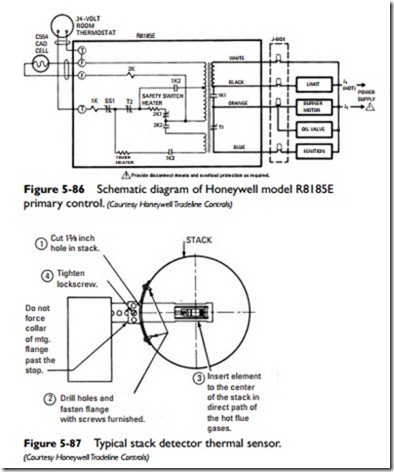
Stack-mounted oil burner primary controls employ thermal sen- sors to detect ignition or flame failure. A typical stack detector thermal sensor (see Figure 5-87) consists of a bimetal element
inserted into the stack (see Figure 5-88). The thermal sensor (com- bustion thermostat) is usually located on the stack where the element will be exposed to the most rapid temperature changes. The thermal sensor should always be mounted ahead of any draft regu- lator. If installed on an elbow, it should be mounted on the outside curve of the elbow.
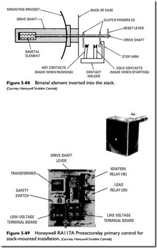
The stack-mounted primary control illustrated in Figure 5-89 combines a Honeywell RA117A Protectorelay control for burner
cycling control and a thermal detector for sensing temperature changes of the flue gases (as high as 1000F° maximum temperature). The safety switch shown on the center-left of the unit is designed to lock out if the flame is not properly established. If the flame goes out during the burner on cycle, the primary control will make one attempt to restart. If the attempt is unsuccessful, the safety switch will lock out. A manual reset is then required in order to restart the burner. The primary control shown in Figure 5-89 is used with a two-wire or three-wire primary controller.
A stack-mounted combination line voltage primary control and flame detector is shown in Figure 5-90. This type of primary control is used with constant-ignition oil burners and is designed for flange-mounting on a stack, flue pipe, or combustion chamber door of a furnace or boiler. It must be used with a line voltage thermostat or controller.


