RECLAIMING REFRIGERANT
One of the means available for reclaiming refrigerant is called the TOTALCLAIM® system. It is furnished to the trade by Carrier, long known for its dominance in the field of refrigeration and air conditioning.
The information in this section is designed to aid the service technician in understanding the construction and operation of the TOTALCLAIM system. A thorough understanding of the system is the most effective tool for troubleshooting.
Description
TOTALCLAIM extracts refrigerant from an air-conditioning or refrigeration system, removes contaminants from the refrigerant, and stores the charge until it is returned to the original system or another system. TOTALCLAIM can determine the level of acid and moisture contamination in the refrigerant through the use of TOTALTEST.
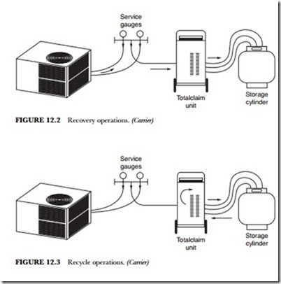
In recovery operations (Figure 12.2) refrigerant is extracted from an air-conditioning or refrigeration sys- tem and temporarily stored in the TOTALCLAIM storage cylinder. In recovery mode, the target system is evacuated to a pressure less than 0 psig. In recovery plus mode, the target is evacuated to a negative pressure of approximately 20 inches Hg (4 psia).
In the recycle mode (Figure 12.3) refrigerant already stored in the storage cylinder is reprocessed through the TOTALCLAIM unit to remove additional contaminants.
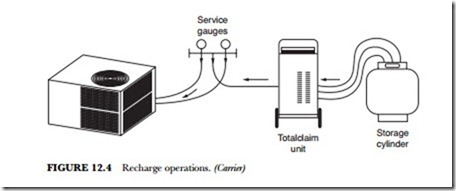
In the recharge mode (Figure 12.4), the refrigerant stored in the TOTALCLAIM storage cylinder is re- turned to the target air-conditioning or refrigeration system.
In the service mode, the internal solenoid valves are positioned so that the TOTALCLAIM system can be evacuated. Service mode would be used when a different refrigerant is to be recovered or when piping connections within TOTALCLAIM must be opened to permit repair.
The test mode permits the service technician to energize individual solenoid valves for the purpose of checking out the energizing paths. This mode is intended solely for control-circuit troubleshooting.
In all modes, the pattern of refrigerant flow is determined by solenoid valves, which are controlled by the microprocessor-based control.
Description and Component Location
The TOTALCLAIM unit is approximately 35 inches (90 cm) high, including the handle. It is 16 inches
(40.7 cm) wide and 10.5 inches (26.5 cm) deep. The TOTALCLAIM unit weighs about 75 pounds (34 kg). It is accompanied by a 50-pound (22.7 kg) capacity D.O.T.-approved refrigerant storage cylinder modified for the TOTALCLAIM application. The hoses required to connect the storage cylinder to the unit are also provided. An external filter dryer is available as an accessory.
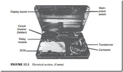
In Figure 12.5 all electrical and electronic controls, except for the solenoid valves, are located in the up- per section. This section contains the control-panel display board, microprocessor control (standard control module), and a relay board. The only replaceable discrete components in the electronics section are the power switch, transformer, compressor/fan motor contactor, and circuit breaker. If a malfunction is traced to the electronic controls, the entire control module, display board, or relay board must be replaced.
Compressor
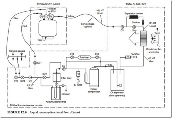
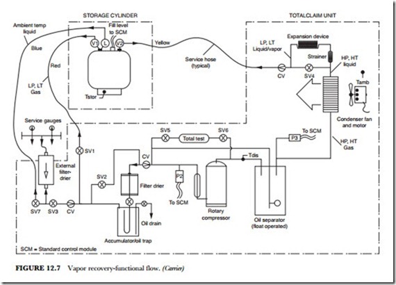
In Figure 12.6 the TOTALCLAIM uses a rotary compressor to pump refrigerant. The compressor is equipped with an external, automatic-reset overload device that trips on excess current or temperature. A discharge temperature thermistor (TDIS) senses the compressor discharge temperature. From here the data is sent to the microprocessor. Both the suction and discharge sides of the compressor are monitored by pres- sure transducers. These transducers send pressure data to the microprocessor.
Oil Separator
The oil separator collects lubricating oil that escapes with the compressor-discharge gas. A float-valve arrangement inside the oil separator returns oil to the compressor when it reaches a predetermined level.
Condenser
The condenser fan blows air across the condenser, which is mounted to the rear wall. It is a copper- tube/aluminum-fin condenser. The ambient air thermistor (TAMB) senses the temperature at the con- denser and sends that data to the microprocessor.
Filter Dryer
The primary filter-dryer is located behind the access door on the side of the unit. The reset switch for the circuit breaker is also located in this section. Knurled, quick-connect fittings permit the filter dryer to be re- moved and installed without the need for tools. The filter-dryer shutoff valve must be turned off to allow the filter dryer to be replaced while the system is under pressure (see Figure 12.7).
Accumulator/Oil Trap
The suction-line accumulator/oil trap intercepts oil coming from the unit being evacuated. An oil drain with a valve and an oil-measurement bottle are provided so that the trapped oil may be removed. Oil must be drained after each use. The oil-drain valve should be opened slowly to prevent excessive release of refrigerant.
The refrigerant hose connections are equipped with caps, which must be in place when the hoses are dis- connected. The hoses have positive shutoff connections at the tank end. The end that connects to the unit is equipped with standard service fittings.
