Heat Recovery
When designing to comply with the Standard, designers can minimize energy use by reducing the energy requirements of a building, and/or by energy recovery. During design, always aim first to minimize energy use before considering energy recovery. The reason is that heat recovery is almost always involved with “low-grade heat.” Low-grade heat is heat that is at a temperature relatively close to the temperature at which it can be used at all. Low-grade heat requires oversized heat transfer surfaces and can often only fill a part of the load. For example, the condenser water from a chiller at 95°F can be used to preheat domestic service water to 90°F but no hotter. A valuable contribution, but it does not do the whole task, since 140°F is the typical requirement.
There are cases where systems can be deliberately chosen to integrate with low heat sources. A good example of this is the use of condensing boilers with radiant floor heating systems. The condensing boiler is a boiler with an additional flue gas heat recovery section. In this additional flue gas cooling section, the water vapor in the flue gas is condensed, causing it to give up its latent heat. This increases the boiler efficiency from a maximum of about 85%, with a flow temperature of 180°F, to about 95% with a 105°F flow temperature. Since radiant flooring operates at low water temperature, the condensing boiler is an excellent match for the radiant floor. Note that condensing only begins to occur below 135°F, so buying a condensing boiler and running it near 135°F will reduce the boiler efficiency since it will not condense the flue gas water vapor.
Energy Recovery Coils: Run-Around Coils
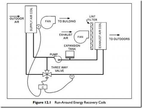
One way to achieve energy recovery is with run-around energy recovery coils. A typical run-around coil arrangement is shown in Figure 12.1.
In summer, the conditioned exhaust air cools the fluid in the exhaust air coil. This fluid is then pumped over to the supply air coil to pre-cool the incoming outside air.
In winter the heat transfer works the other way: the warm exhaust air heats the fluid in the exhaust air coil, which is then pumped over to the supply air coil to heat the cold incoming air.
At intermediate temperatures the system is shut off, since it is not useful.
When outside temperatures are below freezing, the three-way valve is used with a glycol anti-freeze mixture in the coils. In cold weather, some of the fluid
bypasses the supply air coil, to avoid overcooling. The mixture of very cold fluid from the supply air coil and diverted fluid, mix to a temperature that is high enough to avoid causing frost on the exhaust air coil. The maximum amount of cooling that can be achieved with the exhaust air coil is limited by the temperature at which frost starts to form in the coil. This frosting of the exhaust coil effectively sets a limit to the transfer possible at low temperatures.
In Figure 12.1, a filter is shown in front of the exhaust air coil. It is impor- tant to include this filter, since omitting it will soon cause a clogged coil. This is particularly true if the coil runs wet with condensation in cold weather.
The run-around coil system has three particular advantages.
1. There is no possibility of cross contamination between the two air streams. This factor makes it suitable for hospital or fume hood exhaust heat recovery.
2. The two coils do not have to be adjacent to one another. A laboratory building could have the outside air intake low in the building and the fume hood exhaust on the roof, with the run-around pipes connecting the two coils.
3. The run-around coils only transfer sensible heat, and do not condense the water in the exhaust, making them suitable for swimming pool recovery systems.
Heat Pipes
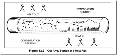
A heat pipe is a length of pipe with an interior wick that contains a charge of refrigerant, as shown in Figure 12.2.
The type and quantity of refrigerant that is installed is chosen for the particular temperature requirements. In operation, the pipe is approximately horizontal and one end is warmed, which evaporates refrigerant. The refrigerant vapor fills the tube. If the other half of the tube is cooled, the refrigerant will condense and flow along the wick to the heated end, to be evaporated once more. This heat-driven refrigeration cycle is surprisingly efficient.
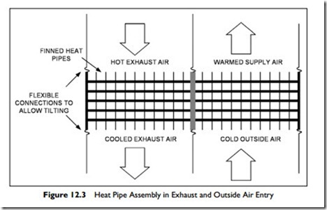
The normal heat pipe unit consists of a bundle of pipes with external fins and a central divider plate. Figure 12.3 shows a view down onto a unit that is mounted in the relief and intake air streams to an air-handling unit. Flexible connections are shown which facilitate the tipping. To adjust the heat transfer, one end or the other end of the tubes would be lifted.
The outside air is cold as it comes in over the warm coil. This warms the air, and the tube is cooled. The cooled refrigerant inside condenses, giving up its latent heat, which heats the air. The re-condensed refrigerant wicks across to the exhaust side and then absorbs heat from the exhaust air. This
heat evaporates the refrigerant back into a vapor which fills the pipe, and is again available to warm the cold outside air.
The usual heat-pipe unit must be approximately horizontal to work well. A standard way to reduce the heat transfer is to tilt the evaporator (cold) end up a few degrees. This tilt control first reduces, and then halts, the flow of refrigerant to the evaporator end, and the process stops.
Figure 12.3 was based on winter operation. In summer, the unit only has to be tilted to work the other way and cool the incoming outside air as it heats the outgoing exhaust air.
The unit is designed as a sensible heat transfer device, though allowing condensation to occur on the cold end can transfer worthwhile latent heat. Effectiveness ratings range up to 80% with 14 rows of tubes. However, each additional row contributes proportionally less to the overall performance. As a result, the economic choice is ten or fewer rows.
A major advantage of the units is very low, to no, cross contamination.
Desiccant Wheels
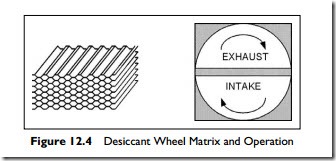
Desiccants are chemicals that are quick to pick up heat and moisture, and quick to give them up again if exposed to a cooler, drier atmosphere. A matrix, as indicated on the left of Figure 12.4, may be coated with such a chem- ical and made up into a wheel several inches thick. In use, the supply air is ducted through one half of the wheel and the exhaust air through the other half.
Let us suppose it is a hot summer day, so the exhaust is cooler and drier than the supply of outside air. The chemical coating in the section of the coil in the exhaust stream becomes relatively cool and dry. Now the wheel is slowly rotated and the cool, dry section moves into the incoming hot, humid air, drying and cooling the air. Similarly, a section is moving from hot and humid into cool and dry, where it gives up moisture and becomes cooler.
The wheel speed, a few revolutions per minute, is adjusted to maximize the transfer of heat and moisture. Control of wheel speed to truly maximize savings is a complex issue, since the transfer of sensible and of latent heat do not vary in direct relation to each other.
The depth of the wheel is filled with exhaust air as it passes into the supply air stream, so there is some cross-contamination. There are ways of minimizing this cross contamination, but it cannot be eliminated. In most comfort situations, the cross contamination in a well-made unit is quite acceptable.


