Air Supply and Venting
Any boiler or furnace fired with a combustible fuel (for example, coal, oil, gas) must be equipped with a piping system to remove smoke and other low-temperature flue gases and to provide sufficient air for combustion. These air supply and venting systems are composed of round pipes and fittings made from sheet metal and resemble ducts in design and construction.
The design and installation of air supply and venting systems are described in the several chapters dealing with furnaces and boilers. See, for example, the appropriate sections of Chapter 11 of Volume 1 (Gas-Fired Furnaces).
Duct Dampers
A duct damper is a device used for controlling the direction or volume of air flowing through a duct.
The ASHRAE defines a damper as being a“ device used to vary the volume of air passing through a confined cross-section by varying
the cross-sectional area. In other words, a damper functions as an obstruction to airflow through the duct; however, it is a movable obstruction that can be adjusted to give various-size openings for the passage of air.
The air volume in an air distribution system may have to be changed between the heating operation and the cooling operation because it generally requires more air at 50°F to cool a house to 75°F than warm air at 160°170 °F to heat a house to 75°F. Bearing this in mind, the ductwork and fan should be sized for whichever
operation (that is, heating or cooling) requires the greater air volume. Volume control dampers may then be installed in the duct system to reduce the air volume during the season that requires the smaller volume.
A damper is usually made in the form of a round or rectangular blade and can be either manually operated or motorized. The ASHRAE lists the following three basic types of dampers:
• Volume dampers
• Splitter dampers
• Squeeze dampers
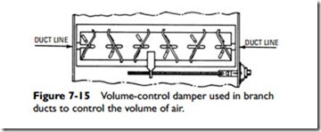
A volume damper or volume-control damper (see Figure 7-15) is installed in a duct to either completely cut off or regulate the flow
of air in the duct. Adjustments of the volume of airflow and resistance can be made with a squeeze damper. A splitter damper is a directional device consisting of a blade hinged at one end and used at locations where a branch run leaves the main duct.
Three examples of volume dampers are (1) slide dampers, (2) hit-and-miss dampers, and (3) butterfly dampers. The slide damper is operated by sliding or pushing a metal plate across the duct. It operates at either full open or full closed position, there being no
practical intermediate setting. A hit-and-miss damper provides volume control with two slotted plates or discs placed adjacent to one another. At full open position, 50 percent of the duct cross-section remains blocked. A butterfly damper consists of a single blade hinged in the middle. At full open position, almost the entire cross- section of the duct is free of blockage.
The adjustment lever for a duct damper should be in an accessible location, and it should be labeled to indicate position settings,
function, and area served. The damper should also be equipped with a positive locking device.
Dampers properly placed in the supply and return ducts of an air distribution system will control the supply of air to a room; how- ever, care should be taken in the placement of these dampers. A damper in a supply duct placed too close to the supply air outlet may disturb the airflow. Excess noise is often the result of improperly placed dampers.
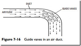
Splitters and guide vanes (see Figure 7-16) are nonmovable sheet-metal partitions placed in stack heads or elbows to reduce air turbulence and to guide the airflow. Air directors are similar devices but are used to direct a portion of the airflow to a branch duct.
A fire damper is a damper designed to close off a duct in order to prevent the spread of flames and smoke. Fire dampers should be placed in branch duct connections that pass through fire walls, fire- rated partitions, or floors. Never install a fire damper in main exhaust ducts and risers. Installation of fire dampers should comply with local ordinances and National Fire Protection Association Standards.
Related posts:
Incoming search terms:
- duct splitter damper
- Air Duct Material Manufacturers mail
- what are the duct used in supply system
- splitter dampers in ducts fig
- splitter damper hvac
- splitter damper hardware
- splitter damper function
- splitter damper
- rectangular HVAC air duct lock forming machine from manufacturer suppliers mail
- guide vanes in ducts
- ducting spliter full open
- duct forming machines suppilers and manufacturies mail
- what is the function of air splitter in air distribution system?
