Drive belts
Correct alignment of the flywheel and drive pulley, and correct tensioning of the drive belt(s), are most important during the installation or replacement of belt(s) or motor. Incorrect alignment and tensioning can result in excessive belt wear, loss of compressor efficiency, and motor failure due to faulty motor or compressor drive shaft bearings.
Alignment
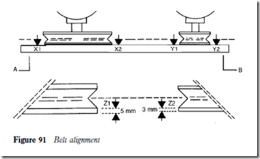
This may be carried out with a piece of string or preferably a straight edge (AB in Figure 91), aligning the drive motor pulley to the compressor flywheel. It is essential that the areas X and Y are aligned accurately. Any variation in the pulley or flywheel thickness must be compensated for when aligning the flywheel and pulley faces (area Z).
Selection
All drive belts are subject to bending and compressing, which will inevitably result in stretching. Centrifugal force also adds to belt stress. The distance between the flywheel and the pulley plays an important part in the amount of stress and force generated during the operation of the motor and compressor.
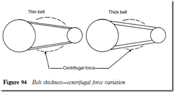
It is important, therefore, that drive belts are selected to the design char- acteristics, i.e. that they are of the correct length, thickness and section. Any increase in centrifugal force will tend to increase the amount of stretch on a belt. A thin belt will create a greater force.
Tension
A loosely fitted belt increases centrifugal force, leads to excessive wear and causes the belt to slip. A belt fitted too tightly may break and have a side effect on shaft bearings.
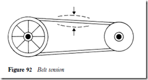
It is said that a belt is too slack when it jumps off the pulley. However, this is an overstatement because even if the belt remains in place it may still be subject to unnecessary flexing, wear and stress. A recognized method of adjusting the belt tension is to allow a maximum of 25 mm (1 in) deflection at the position shown in Figure 92.
Length
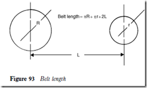
For short belts, that is at up to 1.3 m between shaft centres, the following formula is considered to be accurate enough for belt sizing (Figure 93):
half circumference pulley C half circumference flywheel C twice distance between shaft centres
nR C nr C 2L
For example, if R D 225 mm, r D 75 mm and L D 750 mm, the belt length is given by
706.95 C 235.65 C 1500 D 2442.6 mm ‘ 2.4 m
Thickness
Examples of centrifugal force variation with belts of different thickness are shown in Figure 94.
