Performance characteristics for high-speed machines Compressors
The performance (or characteristic) map of a high-speed compressor is essentially a graphical representation of the functional relationships given in Eq. (2.9b). Figure 2.4 shows a performance map for a transonic fan and Figure 2.5 shows a performance map for a high-speed multistage axial compressor. In both cases, the pressure ratio across the machine is plotted as a function of several fixed values of which is the usual method of presentation. Figures 2.4 and 2.5 also show contours of compressor isentropic efficiency on the same axes.
Each of the constant speed curves on the compressor characteristic terminate at the instability line (often referred to as the surge or stall line). Beyond this point, the operation is unstable. A dis- cussion of the phenomena of surge and stall is included in Chapter 5. At high speeds and low pressure ratios, the constant speed curves become vertical. In these regions of the characteristic, no further increase in is possible since the Mach number across a section of the machine has reached unity and the flow is choked.
A compressor is able to operate anywhere below and to the right of the surge line. However, it is usually constrained to a single operating line, which is set by the flow area downstream of the compressor. A single operating line is shown in Figure 2.4. The design operating line is usually
specified so that it passes as close as possible to the point of peak compressor efficiency. However, its exact position is a matter of judgment for the compressor designer. The term stall margin is often used to describe the relative position of the operating line and the surge line. There are several ways of defining the surge margin (SM) and a fairly simple one often used is
![]() where (pr)o is a pressure ratio at a point on the operating line at a certain corrected speed and (pr)s is the corresponding pressure ratio on the surge line at the same corrected speed. With this definition a surge margin of 20% would be typical for a compressor used within a turbojet engine. Several other definitions of stall margin and their merits are discussed by Cumpsty (1989).
where (pr)o is a pressure ratio at a point on the operating line at a certain corrected speed and (pr)s is the corresponding pressure ratio on the surge line at the same corrected speed. With this definition a surge margin of 20% would be typical for a compressor used within a turbojet engine. Several other definitions of stall margin and their merits are discussed by Cumpsty (1989).
Turbines
Figure 2.6 shows a typical high-speed axial turbine characteristic. The behavior of turbines is very different to that of compressors and this is reflected in the way the characteristic has been presented. Turbines are able to operate with a high-pressure ratio across each stage because the
boundary layers on the surfaces of the turbine blades are accelerating and therefore stable. The high-pressure ratios soon lead to choking in the turbine stator blades and therefore a fixed nondimensional mass flow through the machine. Once the turbine stators are fully choked, the operating point is independent of because the rotation of the blades has virtually no influence on either the turbine pressure ratio or the nondimensional mass flow rate.
As shown by Figure 2.6, it is more revealing to plot the flow capacity and turbine efficiency as a function of the turbine pressure ratio rather than the other way around, since it is usually the pressure ratio across a turbine that is specified and, for a high-speed case, there is limited variation in ![]()
EXAMPLE 2.2
The compressor with the performance map shown in Figure 2.5 is tested at sea level on a stationary test bed on a day when the atmospheric temperature and pressure is 298 K and 101 kPa, respectively. When running at its design operating point, the mass flow rate through the compressor is measured as 15 kg/s and the rotational speed is 6200 rpm. Determine the mass flow rate and rotational speed when the compressor is operating at the design operating point during high altitude cruise with an inlet stagnation temperature of 236 K and an inlet stagnation pressure of 10.2 kPa.
The design pressure ratio of the compressor is 22. Using the compressor characteristic in Figure 2.5, determine the compressor isentropic and polytropic efficiency at the design point. Hence calculate the required power input at the cruise condition. Assume throughout for air that γ 5 1.4 and Cp 5 1005 J/kg/K.
Solution
At cruise and during the test the compressor is operating at its design nondimensional operating point. Therefore, all the nondimensional performance parameters of the compressor will be the same at both conditions.
Specific speed and specific diameter
The turbomachine designer is often faced with the basic problem of deciding what type of machine will be the best choice for a given duty. At the outset of the design process, some overall require- ments of the machine will usually be known. For a hydraulic pump, these would include the head required, H, the volume flow rate, Q, and the rotational speed, Ω. In contrast, if a high-speed gas turbine was being considered, the initial specification would probably cover the mass flow rate, m_ , the specific work, Δh0, and the preferred rotational speed, Ω.
Two nondimensional parameters called the specific speed, Ωs, and specific diameter, Ds, are often used to decide upon the choice of the most appropriate machine (see Balje (1981)). The specific speed is derived from the nondimensional groups defined in Eqs. (2.3a-c) in such a way that the characteristic diameter D of the turbomachine is eliminated. The value of Ωs gives the designer a guide to the type of machine that will provide the normal requirement of high efficiency at the design condition. Similarly, the specific diameter is derived from these groups by eliminating the speed, Ω.
Consider a hydraulic turbomachine with fixed geometry. As shown by Eq. (2.3b), there will be a unique relationship between efficiency and flow coefficient if Reynolds number effects are negligible and cavitation absent. If the maximum efficiency η 5 ηmax occurs at a unique value of flow coefficient Φ 5 Φ1 and corresponding unique values of ψ 5 ψ1 and P^ 5 P^1; it is possible to write
Similarly to specific speed, to form the specific diameter, any pair of expressions in Eqs. (2.13a-c) can be used to eliminate the speed, Ω. In the case of a pump, we divide ψ1/4 by Φ1/2. Thus,
Equations (2.14), (2.15), and (2.17) are dimensionless. It is always safer and less confusing to calculate specific speed and specific diameter in one or another of these forms rather than dropping the
factors g and ρ, which would make the equations dimensional and any values of specific speed or specific diameter obtained using them would then depend upon the choice of the units employed. The dimensionless forms of Ωs (and Ωsp) and Ds are the only ones used in this book. Another point arises from the fact that the rotational speed, Ω, can be expressed in rad/s, rev/s or rpm, and therefore, although Ωs is dimensionless, numerical values of specific speed are sometimes specified in rev/s rather than rad/s. In this book, unless otherwise stated, the speed of rotation is taken to be in rad/s.
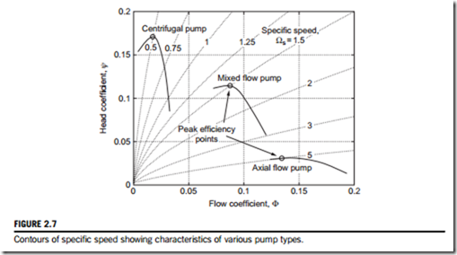
The concept of specific speed just described is illustrated in Figure 2.7. This shows contours of Ωs plotted as a function of flow coefficient, Φ, and head coefficient, ψ, using Eq. (2.14). Also plotted on the same axes are typical characteristics of three types of hydraulic pumps. This plot demonstrates how for a given type of machine, one value of Ωs passes through the operating point of peak efficiency. In other words, once the specific speed is known, the machine type giving peak efficiency can be determined. Figure 2.7 also shows how a low specific speed suits radial machines, since these tend to give a high pressure change to a low mass flow rate. In contrast, axial flow stages with widely spaced blades are suited to high specific speed applications because they impart a small pressure change to a large mass flow rate.
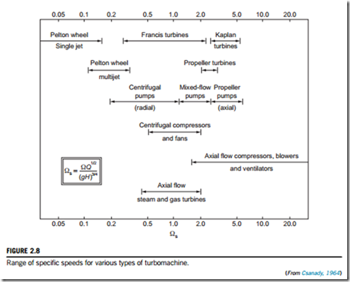
Given that specific speed is defined at the point of maximum efficiency of a turbomachine, it becomes a parameter of great importance in selecting the type of machine required for a given duty. The maximum efficiency condition replaces the condition of geometric similarity, so that any alteration in specific speed implies that the machine design changes. Broadly speaking, each different class of machine has its optimum efficiency within its own fairly narrow range of specific speed. Figure 2.8 shows the ranges of specific speed appropriate to different types of turbomachine. Once the specific speed at the design condition is found, a well-designed machine selected using Figure 2.8 should give the maximum possible design efficiency.
EXAMPLE 2.3
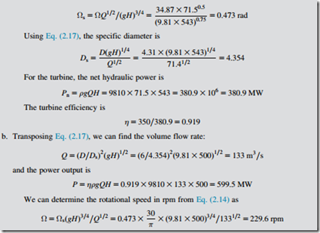
a. A hydraulic turbine with a runner outside diameter of 4.31 m operates with an effective head, H, of 543 m at a volume flow rate of 71.5 m3/s and produces 350 MW of shaft power at a rotational speed of 333 rpm. Determine the specific speed, the specific diameter, and efficiency of this turbine.
b. Another geometrically and dynamically similar turbine with a runner 6.0 m diameter is to be built to operate with an effective head of 500 m. Determine the required flow rate, the expected power output, and the rotational speed of the turbine.
Solution
a. Note: All speeds are first converted to rad/s; therefore, Ω 5 333 3 π/30 5 34.87 rad/s.
Using Eq. (2.14), the specific speed is
The Cordier diagram
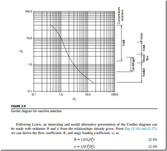
A rough but useful guide to the selection of the most appropriate type and size of compressor, pump, or fan for a given duty and optimum efficiency is obtained by means of the Cordier diagram, Figure 2.9. Although the method was originally devised by Cordier (1953), further details are more readily accessed from the work of Csanady (1964) and, with some added elaboration, by Lewis (1996). Figure 2.9 shows, on the right-hand side, the recommended ranges for various types of turbomachines for which the method applies. It must be mentioned that the line presented is, in fact, a mean curve based upon results obtained from a large number of machines, so it represents a fairly broad spread of results on either side of the line. For many designs, it would be possible to diverge from the line and still obtain high-performance pumps, fans, or compressors.
By introducing the Cordier line data into these last two equations and replotting this information, a new and more definite shape of the optimum machine curves results, shown in Figure 2.10. The new curve is clearly divided into two main parts with centrifugal pumps operating at a fairly constant head coefficient at roughly ψ 5 0.1 over a flow coefficient range of 0.001 # Φ # 0.04 and axial machines operating with a wide range of stage loading coefficients, 0.005 # ψ # 0.05 and also a wide range of Φ. Casey, Zwyssig, and Robinson (2010) show that the shape of the Cordier line and the two distinct parts of the curve in Figure 2.10 are caused by the variation in centrifugal effects in the different compressor types: In radial machines, almost all the pressure change is due to the centrifugal effects generated by a change in flow radius, whereas these effects are absent in axial machines (see Chapter 7).
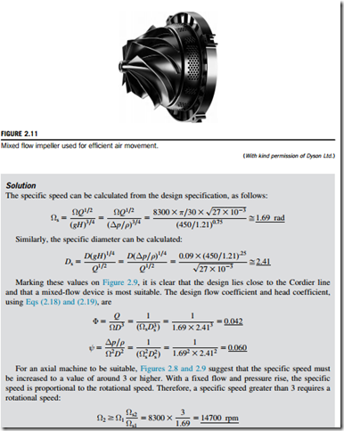
Mixed-flow machines are stuck in between axials and radials with quite a narrow range of both ψ and Φ. However, in some cases, mixed-flow machines are the crucial choice. Lewis (1996) points out that applications that require a high mass flow at a high pressure ratio, such as gas cooled nuclear reactors and hovercraft lift fans, are ideally suited for mixed-flow fans rather than a single- stage axial compressor. Recently, mixed-flow turbomachinery has found application in specialist domestic appliances. Figure 2.11 shows a mixed-flow fan used for air movement.
EXAMPLE 2.4
The mixed-flow fan shown in Figure 2.11 is designed to provide a pressure rise of 450 Pa to air at a volume flow rate of 27 L/s. The impeller design rotational speed is 8300 rpm and its tip diameter is 90 mm.
Calculate the specific speed and specific diameter of the fan and mark the location of the design on the Cordier line in Figure 2.9. Also determine the design flow coefficient and head coefficient. Assuming that the required flow rate and pressure rise cannot be changed, estimate the rotational speed that would be needed for an axial flow fan to be suitable for the design.
Take air density to be 1.21 kg/m3.
Compressible specific speed
Specific speed as defined in Eq. (2.14) has mostly been applied to the design and selection of low- speed and hydraulic turbomachines. However, the notion of specific speed can equally be applied to a compressible flow machine, and it is particularly useful for determining whether an axial or a radial flow machine is best for a particular requirement. As described in Baskharone (2006), the application of the important concept of specific speed to compressible turbomachines has to be modified because of the large variation in the values of volume flow rate, Q, as well as the particular meaning of the head, H. The specific speed when applied to high-speed turbomachines is there- fore expressed in terms of parameters appropriate to compressible flow:
Note that in Eq. (2.20), the isentropic specific work, Δh0s, is used rather than the actual specific work, Δh0. In the case of a compressor, this makes sense since the isentropic specific work can be determined from the required pressure ratio p02/p01 using Eq. (2.7). The required pressure ratio is likely to be known at the outset of the design process, whereas the actual specific work input depends on the compressor efficiency, which in general will not be known. In the case of a turbine, the actual specific work is more likely to be a known requirement. The efficiency can be estimated or the isentropic work approximated to be equal to the actual work required.
Equation (2.20) also requires the density of the working fluid at exit ρe. This can be estimated from ρe 5 pe=RTe, with pe and Te taken as the isentropic static pressure and temperature at exit from the machine. Other definitions are sometimes used, but this is the simplest and any extra uncertainty introduced is likely to be small and will have no effect on the preferred type of machine selected.
EXAMPLE 2.5
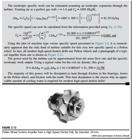
An air turbine is required for a dentist’s drill. For the drill bit to effectively abrade tooth enamel, the turbine must rotate at high speed, around 300,000 rpm. The turbine must also be very small so that it can be used to access all parts of a patient’s mouth and an exit air flow rate in the region of 10 L/min is required for this. The turbine is to be driven by supply air at a pressure of 3 bar and a temperature of 300 K.
Calculate the specific speed of the turbine and use this to determine the type of machine required. Also estimate the power consumption of the turbine and account for how this power is used.
Solution
Putting the quantities into standard SI units,
Related posts:
Incoming search terms:
- characteristics of high performance machines
- specific speed of turbine equation
- specific speed of compressor depends
- SPECIFIC DIAMETER PUMP
- specific diameter
- small axial compressor map
- performance characteristics of low and high speed machines
- performance characteristics for low and high speed machines
- dimensionless specific speed of turbine formula
- compressor performance characteristic diagram
- specific speed of turbine formula


