Schematics and Wiring Diagrams
Schematics and wiring diagrams are the written language of control circuits. It will be impossible for a service technician to become proficient in trouble shooting electrical faults if he or she cannot read and interpret electrical diagrams. Learning to read electrical diagrams is not as difficult as many people first believe it to be. Once a few basic principles are understood, reading schematics and wiring diagrams will become no more difficult than reading a newspaper.
TWO-WIRE CIRCUITS
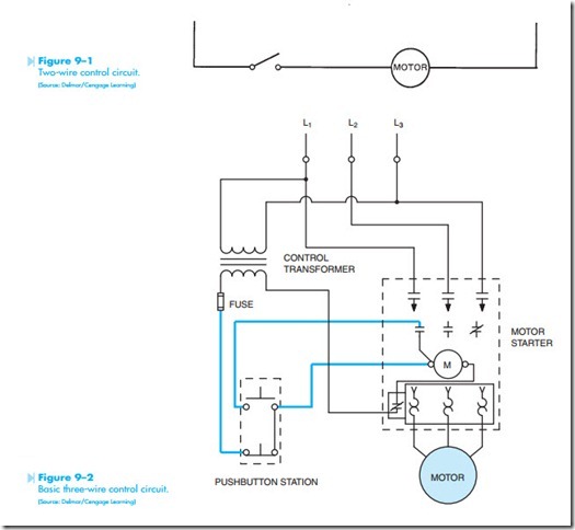
Control circuits are divided into two basic types, the two-wire and the three-wire. Figure 9–1 shows a simple two-wire control circuit. In this circuit, a simple switch is used to control the power applied to a small motor. If the switch is open, there is no complete path for current flow, and the motor will not operate. If the switch is closed, power is supplied to the motor, and it then operates.
THREE-WIRE CIRCUITS
Three-wire control circuits are used because they are more flexible than two-wire circuits. Three- wire circuits are characterized by the fact that they
are operated by a magnetic relay or motor starter. These circuits are generally controlled by one or more pilot devices. Three-wire control circuits receive their name from the fact that three conductors or wires are required to make connection from a start-stop pushbutton station to a motor starter, Figure 9–2.
ELECTRICAL SYMBOLS
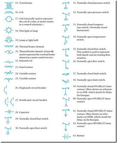
When a person first learns to read, he or she learns a set of symbols that are used to represent different sounds. This set of symbols is generally referred to as the alphabet. When learning to read electrical diagrams, it is necessary to learn the symbols used to represent different devices and components. The symbols shown below are commonly used on control schematics and wiring diagrams. These are not all the symbols used. Unfortunately, there is no set standard for the use of electrical symbols.
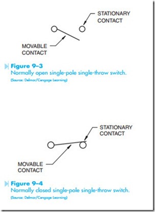
To better understand electrical symbols, it is helpful to understand some of the common terms used to describe these symbols. The terms movable and stationary contacts, for example, refer to electrical contacts located on different components. A simple switch contains both a movable and a stationary contact, Figure 9–3. Stationary contacts refer to contacts that cannot be moved or changed. Movable contacts can be moved from one position to another. The switch shown in Figure 9–3 can also be described as a normally open switch because:
1. The movable contact is shown not touching the stationary contact.
2. The movable contact is drawn below the stationary contact.
Control components are drawn in the position they should be in when the circuit is deenergized or turned off. Normally open means that there is no electrical connection or complete circuit made between the movable and stationary contacts of the switch.
The switch in Figure 9–3 can be described as a single-pole single-throw (SPST) switch. Single pole indicates that the switch contains only one movable contact. Single throw means that the movable con- tact will complete a circuit when thrown or moved in only one direction.
A normally closed single-pole single-throw switch is shown in Figure 9–4. The switch is normally closed because:
1. The movable contact is shown touching the stationary contact.
2. The movable contact is drawn above the stationary contact.
When a component is normally closed it indicates that a complete circuit exists through the component.
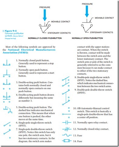
Although these basic rules apply to switches, they do not necessarily apply to all control components. When possible, components are generally drawn to indicate how they function. Pushbuttons, for example, are drawn differently than switches. A normally closed pushbutton is drawn with the movable contact below instead of above the stationary contacts, Figure 9–5. It is drawn in this manner to illustrate that when pressure is applied to the spring-loaded stationary contact it will cause the movable contact to move downward, breaking the connection between the two stationary contacts. A normally open pushbutton symbol is drawn with the movable contact above instead of below the stationary contacts. Pressure forces the movable contact downward, bridging the gap between the two stationary contacts and completing a circuit.
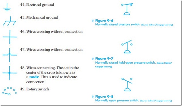
The contact symbols shown are standard and relatively simple to understand. There can be instances, however, in which symbols can be used to show something that is not apparent. For example, the symbol for a normally closed pressure switch is shown in Figure 9–6. Notice that this symbol not only shows the movable arm making contact with the stationary contact, but it also shows the movable arm drawn above the stationary contact. In Figure 9–7, the contact arm is shown not making connection with the stationary contact. This symbol, however, is not a normally open contact symbol because the contact arm is drawn above the stationary contact. This symbol indicates a normally closed held-open pressure switch. This symbol is indicating that the switch is actually connected as a normally closed switch, but pressure is used to keep the con- tact open. If pressure decreases to a certain point, the switch contact will close.
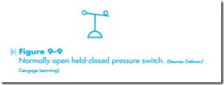
Figure 9–8 shows a normally open pressure switch. Notice that the contact arm is drawn below the stationary contact. Figure 9–9 shows the same symbol except that the movable arm is making connection with the stationary contact. This symbol represents a normally open held-closed pressure switch. This switch symbol indicates that the pressure switch is wired normally open, but pressure holds the contact closed. If the pressure decreases to a certain level, the switch will open and break connection to the rest of the circuit.
