Carnot Refrigeration Cycle
Inversion of the Carnot cycle gives the Carnot refrigeration (or heat pump) cycle with the following processes:
1-2 rev. adiabatic (isentropic) compression from TL to TH
2-3 rev. isothermal compression at TH
3-4 rev. adiabatic (isentropic) expansion from TH to TL
4-1 rev. isothermal expansion at TL
The process curves in the p-v- and T-s-diagrams are depicted in Fig. 8.3. As before, the curve in the T-s-diagram is independent of the working fluid, while the p-v-diagram is sketched for an ideal gas as working fluid.
The analysis of the inverse cycle is just analog to the analysis in the preceding section, and we do not go through the details. The well-known coefficients of performance for a Carnot refrigerator and a Carnot heat pump can be easily read from the T-s-diagram as
Internal Combustion Engines
In an internal combustion engine, heat is provided to the system by burning an air-fuel mixture inside the system. Engine operation requires the exchange of the working fluid after one cycle is completed, to bring in new fuel and oxygen. Accordingly, internal combustion engines exchange mass with their surroundings. Nevertheless, during the working cycle the system is closed, and thus internal combustion engines can be analyzed as closed systems.
Internal combustion engines are the dominant power source for cars, trucks, ships and non-electric trains. In cars one usually finds Otto engines, while in trucks, ships and trains Diesel engines are used.
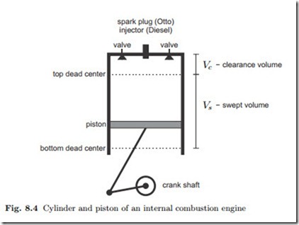
Figure 8.4 shows a sketch of a single piston-cylinder assembly of an internal combustion engine. The piston is connected through rods to the crankshaft.
The crankshaft is driven through the expansion process, which pushes the piston down, and it provides the work for the compression processes. Most engines have several cylinders that run through the cycle with a phase shift to ensure even load on the crankshaft; in single cylinder engines a fly wheel might be mounted to the crankshaft.
As the crank shaft turns, the piston moves between bottom dead center and top dead center. The volume the piston moves through is known as the swept volume Vs, the remaining volume at top dead center is the clearance volume Vc. Valves allow the exchange of working fluid with the surroundings.
The main difference between Otto and Diesel engine is that an Otto engine draws in air-fuel-mix while in a Diesel engine the fuel is injected into the cylinder later in the process. The combustion process in the Otto engine is triggered by a spark plug, while in the Diesel engine the fuel begins to burn as soon as it is injected. Accordingly, the figure shows spark plug (for Otto engine) and injector (for Diesel engine).
We now follow through the processes in a four-stroke engine, starting at top dead center:
Stroke I: The first stroke is the intake stroke. The valves are open, and as the piston moves towards bottom dead center air-fuel-mix (Otto) or air (Diesel) spark plug (Otto) injector (Diesel)
enters the cylinder. Since the valves are open, the pressure in the cylinder is nearly constant. Whence bottom dead center is reached, the valves close.
Stroke II: In the second stroke the piston returns to top dead center. Since the valves are closed, the working fluid (air-fuel-mix or air) is compressed. The process is fast, and nearly adiabatic, pressure and temperature increase. The compression work is provided by the crankshaft. Shortly before the piston reaches top dead center, the combustion is triggered, either by firing the spark plug (Otto), or by injecting fuel which begins to burn in the hot air (Diesel).
Stroke III: As the fuel burns, the temperature of the working fluid is further increased. The hot combustion gas expands in the third stroke, as the piston returns to bottom dead center. The expansion is fast, nearly adiabatic, pressure and temperature decrease. The expansion work is transferred to the crankshaft.
Stroke IV: For the last of the four strokes the valves open, which leads to a sudden pressure drop. The piston returns once more to top dead center and pushes the expanded combustion products out. This is the exhaust stroke.
We summarize the processes in the four strokes in the following list:
Stroke I : intake valve open
Stroke II : compression, combustion starts valve closed
Stroke III : combustion continues, expansion valve closed
Stroke IV : exhaust valve open
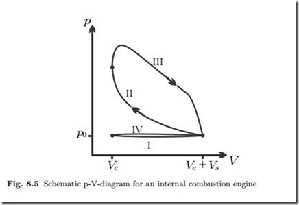
A rough schematic p-V-diagram for all four strokes is shown in Fig. 8.5.
During strokes I and IV the valves are open, and the mass in the cylinder changes. As indicated in the p-V-diagram, in real engines there is a small depression during intake, and a small compression during exhaust, which we ignore. Thus, assuming that during intake and exhaust the pressure equals the exterior pressure p0, the piston work for the two processes is WI = p0Vs and WIV = −p0Vs. The work for these two strokes just cancels,WI +WIV = 0, and does not need to be considered further.
During strokes II and III the valves are closed, and the working fluid goes through a closed system cycle. Due to the chemical processes occurring in the combustion processes, the full analysis of this closed cycle is difficult.
However, the ratio between the amounts of air and fuel is rather large.
Therefore, the amount of fuel can be ignored for a basic analysis, and the working fluid can be considered as air for the complete cycle. This leads to the following modelling assumptions:
(a) The working fluid is air.
(b) The energy that is supplied through the combustion of fuel can be described as a heat transfer into the system.
(c) The exchange of the working fluid in exhaust and intake during which
hot expanded combustion product is exchanged against cold precombustion working fluid can be considered as a heat exchange with the surroundings.
This air standard analysis allows to study internal combustion engines in a simplified yet significant manner. Further simplifications will appear in the following sections which deal with the Otto and Diesel cycles, and some variants.
Otto Cycle
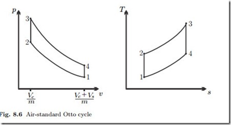
The Otto cycle is named after Nicolaus.A. Otto (1832-1891), who build the first working internal combustion engine. In the Otto cycle, the fuel is mixed into the air outside the cylinder by injection, so that air-fuel mix enters the engine. The compression and expansion processes are assumed to be adiabatic—the processes are fast, and there is hardly time for effective heat exchange. When the spark plug ignites the compressed air-fuel-mix, the mix- ture explodes. The reaction is so fast, that the piston does not move much, and for modelling we describe this as an isochoric heat transfer into the work- ing fluid. Thus, the compression and expansion strokes of the Otto engine can be modelled as
The simplified analysis shows that the compression ratio r is the most important parameter for the evaluation of the Otto cycle. Under the cold air assumption the thermal efficiency depends solely on the compression ratio, and it grows with increasing compression ratio. Obviously, one will aim for large compression ratios to have efficient engines.
The compression ratio cannot be arbitrarily large. As the air-fuel-mix is compressed, its temperature increases, T2 = T1rk−1 . When the temperature of the air-fuel-mix reaches its auto-ignition temperature, it will start to re- act before the spark plug induces the explosion at the appropriate point in the process. Premature combustion, known as engine knocking, reduces the power output since it leads to increased pressure during compression, and, even more importantly, it damages the engine. To prevent knocking, the compression ratio must be limited to values which guarantee that auto-ignition cannot occur. High grade fuel, i.e., gasoline with larger octane numbers, has a higher auto-ignition temperature, and must be used in engines with larger compression ratios.
Typical values for the compression ratio in Otto engines are between 8 and 12. These values yield efficiencies for the idealized cycle discussed above between 0.565 and 0.63. Real engines have about 30% loss to irreversible processes (friction, heat transfer) within the engine, and another 30% loss to friction in the drive train, so that their actual efficiency is η = 0.7 × 0.7 × ηOtto = 0.28 (for r = 8).
Since the working cycle of the engine happens during only two of the four strokes (recall that inlet and exhaust work cancel), the power delivered by an engine which runs at a frequency n˙ is


