Cooling Towers
Cooling towers are a particular type of big evaporative cooler.
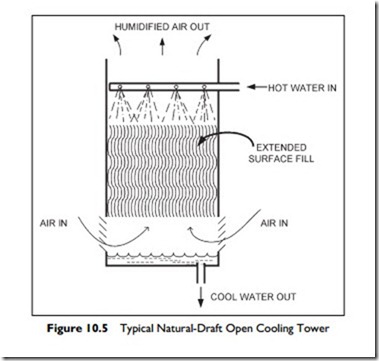
The following description details the sequence of activity in the natural-draft tower, shown in Figure 10.5:
1. Hot water (typically at 95°F,) is sprayed down onto an extended surface “fill.” The fill normally consists of an array of indented plastic sheets, wood boards, or other material with a large surface area.
2. The water coats the fill surface and flows down to drop into the sump at the bottom.
3. At the same time, air is entering near the bottom and rising through the wet fill.
4. Some of the descending water evaporates into the rising air and the almost saturated air rises out of the tower.
5. The latent heat of evaporation, absorbed by the water that does evaporate, cools the remaining water.
6. The cooled water in the sump is then pumped back to the chiller to be reheated.
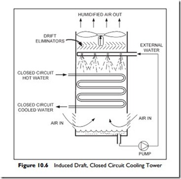
The cooling performance and consistency of operation under various weather conditions can be greatly improved by using a fan to either drive (forced draft) or draw (induced draft) the air through the cooling tower. The addition of a fan increases the speed of the air flowing through the tower, and smaller water drops
may become entrained in the air stream. These drops, if allowed to escape, would be wasted water and could cause wetting of nearby buildings or vehicles. Therefore an array of sheets, called “drift eliminators” is included to catch the drops and return the water to the spray area.
In the open cooling tower, the condenser water is exposed, or open, to the air and it will collect dirt from the atmosphere. Strainers will remove the larger particles but some contamination is inevitable. This contamination can be avoided by using a closed-cooling tower, as is shown in Figure 10.6. Here, the fluid to be cooled is contained in a coil of pipe in place of the fill. This closed tower is an induced-draft tower (the fan draws the air through the tower) and includes drift eliminators.
The figure shows water in the closed coil. Alternatively, refrigerant can be passed through the coil and then the refrigerant pipe loop in the tower is the refrigerant circuit condenser.
In a typical cooling tower, at full load, the closed circuit fluid, water or refrigerant, can be cooled 30–35°F cooler than with an air-cooled coil. This substantially increases the performance of the refrigeration system.
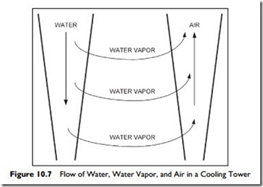
Now that you understand the physical arrangement of the cooling tower, let us consider what is going on inside of the tower. Figure 10.7 shows the basic operation of the cooling tower. On the left, the warm water is falling and becoming cooler while on the right, air rises through the tower and becomes more saturated with water vapor. The evaporating water absorbs its latent heat of evaporation from the surrounding air and water before it is carried up and out of the tower in the flow of air. In effect, the air is a vehicle for removing the evaporated water.
The cooling performance of the tower is dependent on the enthalpy of the ambient air entering the tower. Remember, the drier and cooler the air,
the lower its enthalpy. The lower the enthalpy of the entering air, the greater the evaporation, and therefore, the greater cooling performance.
Surprisingly, the temperature of the air may rise, stay the same or fall as it passes upwards through the tower.
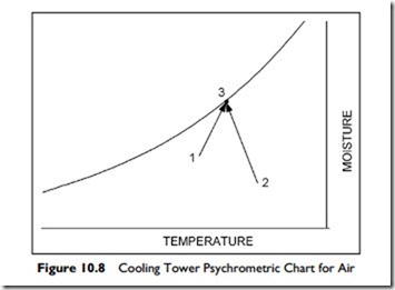
Look at Figure 10.8, and consider these two scenarios:
Scenario 1: Air at Condition 1, enters the tower and is heated and humidified as it rises through the tower, to leave the tower virtually saturated at Condition 3. As the water cools, it provides heat to raise the air temperature.
In this first situation, from Condition 1 to Condition 3, the amount of water evaporated to absorb latent heat was equal to the reduction in the water enthalpy less the cooling provided by the cool air being warmed:
Total latent heat of evaporation = Reduction in water enthalpy – air cooling effect
Scenario 2: In contrast, when warmer air, at roughly the same enthalpy, enters the tower at Condition 2, it will be cooled and humidified as it passes through the tower to leave at Condition 3. The reduction in air temperature is achieved through additional evaporation.
In this situation, from Condition 2 to Condition 3, the amount of water evaporated to absorb latent heat was equal to the reduction in enthalpy of the water plus the heat required to lower the air temperature:
Total latent heat of evaporation = Reduction in water enthalpy + air heating effect
Overall, the tower has approximately the same cooling effect on the water for entering air with the same enthalpy whatever the entering air temperature. However, with the same enthalpy, as the air becomes hotter and dryer more evaporation will take place.
The tower capacity can be reduced in several ways. The fan can be cycled on-and-off, but the frequent starts are very hard on the motor. Better, for both energy conservation and motor life, is to use a two-speed motor and cycle between high, low and off. For slightly better control and energy savings, a variable speed fan can be used.
The water that is evaporated leaves behind any dissolved chemicals. At full load this can be as much as 1% of flow. In addition, the water cleans the air, removing dust and debris. Since the water is warm and full of nutrients, it is an ideal site for bacterial growth, legionella in particular. It is thus critical that the tower is regularly cleaned of dirt buildup and treated, to prevent biological growth.
The Next Step
We have considered components, systems and, in this chapter, central plant. Along the way, equipment has been ‘controlled’ and energy saving has been mentioned. In the next chapter, Chapter 11, we will focus on controls and how they work. We will revisit several of the systems you have already learnt about, and consider their particular control features. Then after controls, we will consider energy conservation in Chapter 12.


