STEAM BOILER FITTINGS AND ACCESSORIES
The boilers used in steam heating systems are fitted with a variety of devices designed to insure the safe and proper opera tion of the boiler. These boiler fittings and accessories can be di vided by function into two basic categories: (1) indicating or measuring devices, and (2) controlling devices. Sometimes both functions are combined in a single unit.
Indicating devices include water gauges, pressure gauges, and other similar types of equipment that provide information about the operating conditions in the boiler. They are designed to indi cate temperatures, pressures, or a water level that fall outside the design limits of the boiler. Controlling devices include boiler equipment designed to cause changes in these conditions. For example, pressure relief valves are used to relieve excess pres sure in the boiler.
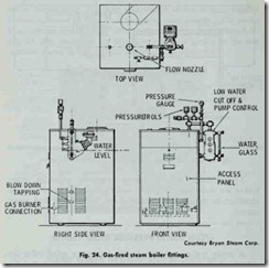
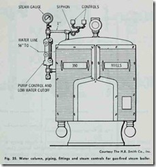
Typical fittings and accessories commonly found on steam boilers are illustrated in Figs. 24 and 25. A steam boiler is easily identified by an externally mounted low water cutoff and pump control.
STEAM BOILER PRESSURE RELIEF VALVES
A steam boiler is equipped with a pressure relief valve (or valves) which opens and releases excess steam at or below the maximum allowable working pressure of the boiler. These are pop safety relief valves designed to comply with the requirements of the ASME Boiler and Pressure Vessel Code.
On the low-pressure boilers used in residential steam heating systems, the pressure (or safety) relief valve is generally preset to open and release steam when a maximum pressure of 15 psi is reached in the boiler. The valve closes when the steam pressure once again falls below 15 psi.
WATER GAUGES
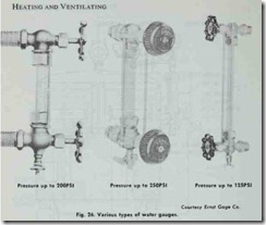
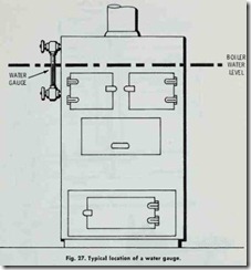
Water gauges are used on both steam and hot-water space heating boilers to indicate the water level. Some examples of the different types of water gauges used on boilers are shown in Fig.26. Fig. 27 illustrates the typical location of a water gauge on a boiler.
A water gauge is used to visually check the level of water in the boiler. If the water level in the boiler is high enough, the glass tube will be approximately half full. If no water is showing in the tube, the boiler must be turned off and refilled to the pro per level. Do not add the water until the boiler has had time to cool off.
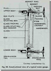
The construction of a typical water gauge is shown in Fig. 28. The glass tube of the water gauge must be long enough to cover the safe range of water level in the boiler. The ends of the water gauge are connected to the interior of the boiler by fittings lo cated above the safe high water level and below the safe low water level.
WATER COLUMNS
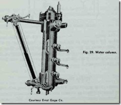
A water column (Fig. 29) is a boiler fitting which combines tyro cocks, a water gauge, and an alarm whistle in a single unit. A float in the column activates an alarm whistle when the water drops below a safe level.
STEAM GAUGE
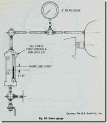
The difference between the pressure found on the inside of a boiler and the pressure on the outside of it is indicated by a steam gauge (Fig. 30). This is a gauge pressure reading and should not be confused with absolute pressure. A steam gauge is used to measure the steam pressure at the top of the boiler. Gen erally a reading of 12 psi (pounds per square inch) indicates a dangerous uild up of pressure in low-pressure steam heating boilers. The boiler should be shut down before the pressure ex ceeds this level.
If the steam gauge is operating properly, the needle (or pointer) will move with each change of pressure inside the boiler. Shut off the steam and the gauge needle should drop to zero; turn on the steam and the needle should rise to the correct reading. It is very important that the steam gauge be regularly checked to insure that it is operating properly.
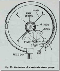
The steam gauges used on boilers operate on the bent-tube principle; that is to say, the tendency of a bent or curved tube to assume a straight position when pressure is applied. As shown in Fig. 31, one end of the curved tube is attached in a fixed position to a pigtail (connector tube) which is, in turn, attached to the boiler. The gauge needle is mounted on a rack-and-pinion gear attached to the free end of the curved tube. The pressure in the curved tube causes its free end to move slightly in its effort to assume a straight position. This slight movement is multiplied by the rack-and-pinion gear, causing the needle to rotate and indi cate the steam pressure.
STEAM GAUGE PIGTAILS
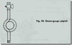
A steam gauge pigtail (Fig. 32) is a length of tubing with one or more loops in it used to connect the steam gauge to the boiler. It functions as a protective device by preventing live boiler steam from coming into contact with the working parts of the gauge. The steam is denied passage by condensation which forms in the loop (or loops) of the pigtail. It is recommended that the steam gauge pigtail be filled with water before it is attached to the boiler. It should be attached to the boiler in a position where heat and vibration will be at a minimum.
