Combustion Chambers for Conversion Oil Burners
A combustion chamber for a conversion oil burner should be constructed of lightweight 2000°F insulating firebrick. With lightweight refractory materials, there is no long smoky delay waiting for the firebox to reach the temperature necessary for complete combustion.
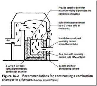
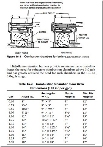
Different types of combustion chamber construction are shown in Figures 16-2 and 16-3. The shape of the combustion chamber will be determined by the shape of the boiler or furnace.
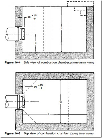
The combustion chamber area (space) is equal to the inside width of the boiler times the length times the distance from the combustion chamber floor to the crown sheet. It is recommended that 1 ft3 be provided for each boiler horsepower, or 3 ft3 per gph oil-fired.
The floor area of the combustion chamber should be based on 100 in2 per gph of oil (see Table 16-2 and Figures 16-4 and 16-5). The minimum side wall height should conform to the recommended measurements listed in Table 16-2.
An overhang in the form of stepped corbels will deflect hot gases from impingement on the heat exchanger surfaces, increase combustion chamber temperatures, and thereby promote good combustion.
Provide corbel or baffle for maximum wiping of products and complete combustion Build combustion chamber up to 2″ above cold air return duct Install sleeve and pack insulating cement around burner tube Seal front with insulating cement (add 10% portland)
When flue outlet and target wall are on same end, use corbel and locate combustion chamber for maximum contact of products with crown sheet


