When installing air conditioning equipment it is important to use the proper size wire. If wire is used that is larger than needed, it is an unnecessary expense. If wire is used that is too small, it will cause excessive voltage drop and damage the equipment.
WIRE RESISTANCE
Most people think of wire as having zero resistance. In fact, many electrical calculations are made that assume the resistance of the wire is so little that it is negligible. In actual practice, however, all wire has resistance. There are four factors that determine the resistance of a piece of wire. The factors are:
1. The diameter of the wire.
2. The material the wire is made of.
3. The length of the wire.
4. The temperature of the wire.
AREA
The cross-sectional area of wire is measured in circular mils. The circular mil area of a wire can be found by finding the diameter of the wire in is a piece of wire one circular mil in diameter and one foot long. If the resistance of a mil-foot of different types of wire is found, a mathematical formula can be used to determine the resistance of different types, sizes, and lengths of wire. This formula is:
squaring that number. (Squaring a number means to multiply that number by itself.) For example, assume a piece of wire is measured with a microme- ter and is found to have a diameter of 8 thousandths of an inch (.008). The circular mil area of the wire is 64 (8 X 8 = 64). Notice that 64 is written as a whole number, not a decimal number. A wire that has a diameter of .064 inch has a circular mil area of 4096 (64 X 64 = 4,096).
The circular mil area of stranded wire is deter- mined by finding the area of one of the strands and then multiplying by the number of strands. For example, assume that a wire has 24 strands of wire that are .012 inches in diameter. The area of one wire is 144 CM (circular mils). The entire conductor has a circular mil area of 3,456 CM (144 X 24 = 3,456). Large wire is generally stranded to make it easier to bend.
The larger the diameter of a wire, the less resistance it will have and the more current it can carry, Figure 6–1. Current flowing through a wire is very similar to water flowing through a pipe. A large wire can carry more current at a specific voltage than a small wire. A large pipe can carry more water at a specific pressure than a small pipe.
MATERIAL
A standard measurement used for finding the resistance of wire is the mil-foot. A mil-foot of wire
Where: K = the ohms per mil-foot of the wire.
L = the length of the wire in feet.
CM = the circular mil area of the wire.
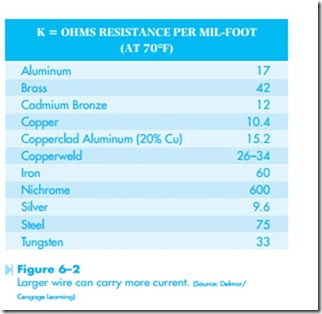
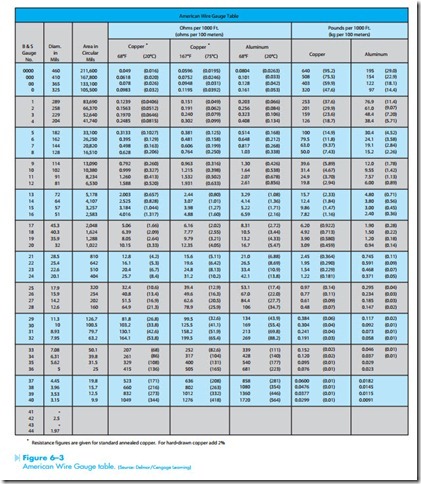
The table in Figure 6–2 gives the resistance of different types of wire in ohms per mil-foot. Using the table shown in Figure 6–3, the diameter and circular mil area for different sizes of wire can be found.
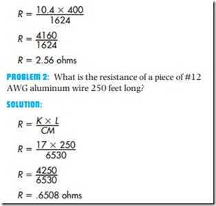
PROBLEM 1: What is the resistance of a piece of #18 AWG (American Wire Gauge) copper wire 400 feet long?
SOLUTION: First, state the formula to be used.
![]() Second, substitute known numeric values in the formula. The value of K can be found in the table shown in Figure 6–2. The K value for copper is
Second, substitute known numeric values in the formula. The value of K can be found in the table shown in Figure 6–2. The K value for copper is
The CM area of #18 AWG wire can be found from the chart in Figure 6–3. The circular mil area of #18 AWG wire is 1624 CM. If these values are substituted in the formula for letters, the formula will be:
TEMPERATURE
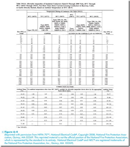
The resistance of a piece of wire is also affected by temperature. As the temperature increases, the resistance of wire increases also. Notice that the charts in Figures 6–2 and Figure 6–3 state the resistance of wire at a specific temperature. Most wire tables will provide some means for determin- ing the resistance of wire as temperature increases. Figure 6–4 shows Table 310.16 of the National Elec- trical Code®. Notice that at the bottom of the table ampacity correction factors are given.
INSULATION
The type of insulation around the wire also partly determines the amount of current the wire is permitted to carry. Some types of insulation can withstand more heat than others, and are, there- fore, permitted to carry more current. For example, in Table 310.16, the type of wire insulation is listed at the top of each column. Notice the different temperature ratings for the types of insulation listed. Also notice the amount of current a wire is permit- ted to carry for different types of insulation. Find a #2 AWG conductor on the far left-hand side of the wire table. Notice the different amounts of current this conductor is permitted to carry with different types of insulation.
VOLTAGE RATING
Wire also has a voltage rating. The voltage rating of wire has nothing to do with the type of material the wire is made of or its diameter. The voltage rat- ing is determined by the type of insulation. Most wire used in industry has a voltage rating of 600 volts. The amount of voltage the insulation can effectively hold off is determined by the material the insulation is made of and its thickness.
SIZING CONDUCTORS FOR HERMETICALLY SEALED COMPRESSORS
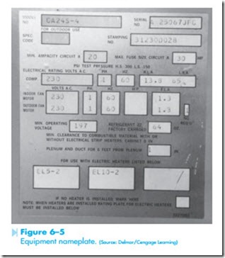
Requirements for the installation of hermetically sealed compressors are covered in Article 440 of the National Electrical Code ®. Note that this sec- tion covers hermetically sealed units only and does not apply to separate motor and compressor units. NEC ® Section 440.6(A) states that the rated-load current marked on the nameplate of the equipment is to be used in determining the rating or ampacity of the disconnecting means, branch circuit conduc- tors, controller, fuses or circuit breakers, ground fault protection equipment, and overload protection. If the rated-load current is not shown on the equipment nameplate, the rated load current shown on the compressor is to be used. Note the difference
between the equipment nameplate and compressor nameplate. The equipment nameplate is generally shown on the unit itself, Figure 6–5. The compres- sor nameplate is located on the compressor.
NEC® Section 440.6(A) Ex. 1 states that where so marked, the branch circuit selection current shall be used instead of the rated load current to deter- mine the rating or ampacity of the disconnecting
means, branch circuit conductors, controller, short circuit protective device, and ground fault protective device. NEC® Section 440.32 states that for a single motor compressor, the branch circuit conductors shall have an ampacity not less than 125% of either the motor compressor rated load current or the branch circuit selection current, whichever is greater. As a general rule the branch circuit selection current will be greater than the compressor rated load amps because the selection current includes any indoor and/or outdoor fans.
Termination Temperature
Another factor that must be taken into consideration is the temperature rating of different terminations. The termination is the point of attachment for conductors such as circuit breakers, disconnects, switches, and so forth. NEC® Section 110.14(C) basically states that the temperature rating of the termination cannot be exceeded. Although a wire with a higher temperature rating may be used, the ampacity of the wire must be selected on the basis of the lowest temperature rating in the circuit. Type THHN insulation has a temperature rating of 90°C, but assume that it is connected to a device with a temperature rating of 75°C. The ampacity of the wire would have to be selected on the basis of 75°C, not 90°C.
Occasionally the temperature rating of a device will be listed on the device or in the manufacturer’s literature, but as a general rule it is not known. For this reason, the National Electrical Code® states that conductors for circuits rated at 100 amperes or less will be selected from the 60°C column, and con- ductors rated over 100 amperes are to be selected from the 75°C column. An exception to this is if the insulation type is rated less than 75°C as is the case with type TW and UF. If either of these two types of insulation are employed, the ampere rating of the conductor must be determined from the 60°C column regardless of the circuit current.
EXAMPLE
Assume that an equipment nameplate lists the rated load amps (RLA) of the compressor at 14.8 amps and the circuit selection current at 22 amps. To determine the correct conductor size for this unit, multiply the larger of the two rating by 125%.
22 X 1.25 = 27.5 amps
The next step is to determine the conductor size from NEC® Table 310.16. It will be assumed that cop- per conductors with type THWN insulation will be used for this installation. Although THWN insulation is located in the 75°C column, the conductor size will be selected from the 60°C column because the total circuit current is less than 100 amperes. Table 310.16 indicates a #10 AWG conductor is the closest size without going under 27.5 amperes. A #10 AWG conductor will be used for this installation.
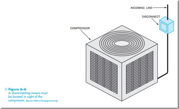
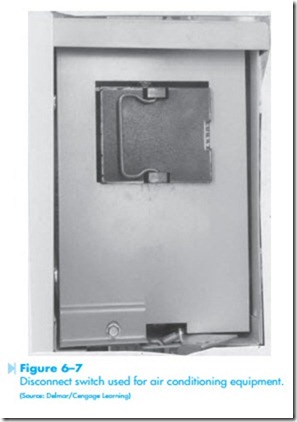
The National Electrical Code® also requires that a disconnecting means be located within sight from and readily accessible to the air conditioning or refrigeration equipment, Figure 6–6. The NEC® does permit the disconnect to be installed on or within the equipment provided it is not installed on a panel that is designed to allow access to the equipment. The disconnect may be located away from the air conditioning or refrigeration equipment provided there is a working clearance of at least 30 inches to allow service accessibility. This is to enable the service technician to disconnect power from the unit without having to enter the building to find the main
TESTING FOR EXCESSIVE VOLTAGE DROP
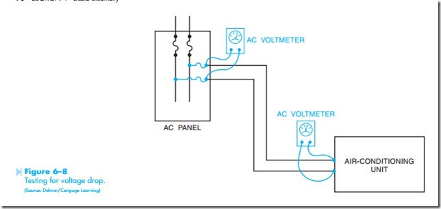
Testing a unit for excessive voltage can be done with a voltmeter. First, test the voltage at the panel with the unit turned off. Assume this voltage to be 240 volts. Next, start the air conditioning unit and again check the voltage at the panel. If the voltage remains unchanged, it is an indication that there is no voltage drop at the panel and that all connections for the part of the circuit are good. If there is excessive voltage drop at the panel, it is an indication of bad connections, or the service entrance is too small for the load. For this example, assume the voltage remains at 240 volts when the unit is turned on. Next, check the voltage at the unit, Figure 6–8. If there is a significant voltage drop at the unit, it indicates that the wire size is too small and that too much voltage is being used to push current through the wire. This problem can be corrected by connecting larger wires from the panel to the unit.

