Inductance
Alternating-current circuits contain three basic types of loads. These are (1) resistive, (2) inductive, and (3) capacitive.
RESISTIVE CIRCUITS
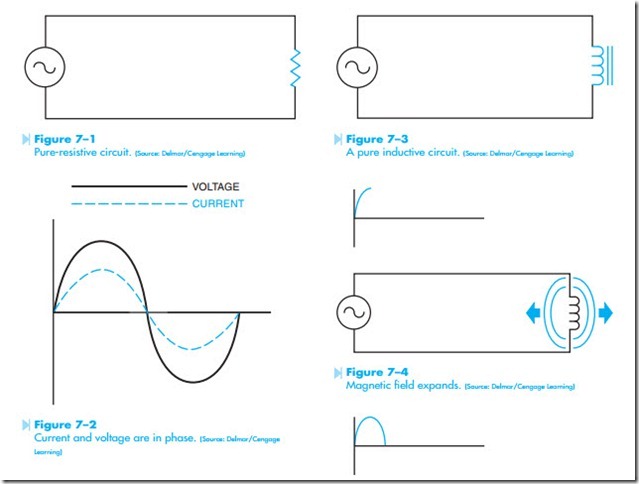
The simplest of the AC loads is a circuit that contains only pure resistance, Figure 7–1. In a pure- resistive circuit, the voltage and current are in phase with each other, Figure 7–2. Voltage and current are in phase when they cross the zero line at the same point, and have their peak positive and negative values at the same time. A pure-resistive circuit is very similar to a direct-current circuit in the respect that true power or watts is equal to the voltage times the current. Examples of pure-resistive circuits are the heating elements of an electric range, an electric hot-water heater, and the resistive elements of an electric furnace.
INDUCTIVE CIRCUITS
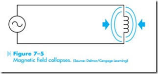
An inductive circuit contains an inductor or coil as the load instead of a resistor, Figure 7–3. The two most common types of inductive circuits are motors and transformers. Inductors are measured in units called the henry. The unit of inductance is named in honor of Joseph Henry, a physicist who studied electricity. The electrical symbol for inductance is L. Inductors differ from resistors in several ways. One way is that the current of an inductor is not limited by the resistance of the coil. When an inductor is connected into an AC circuit and the volt- age begins to rise from zero toward its peak value, a magnetic field is created around the coil, Figure 7–4. As the expanding magnetic field cuts through the wires of the coil, a voltage is induced in the coil. The voltage induced in a coil is always opposed to the voltage that creates it. As the applied voltage begins to drop from its peak value back toward zero, the magnetic field around the inductor begins to collapse, Figure 7–5. Notice that the induced volt- age is opposite in polarity to the applied voltage. An induced voltage is 180° out of phase with the applied voltage, Figure 7–6.
Because the induced voltage is opposed to the applied voltage, it will limit current flow through the circuit just as resistance will. Although the induced voltage of a coil will limit the current flow “like” resistance, it is not resistance and cannot be treated as resistance. The unit of measure used to describe the current-limiting effect of an induced voltage is reactance and is given the electrical symbol X. Because this reactance is caused by an inductance, it is called inductive reactance and is given the electrical symbol XL (pronounced X sub L). Inductive reactance is measured in ohms just as resistance is.
The inductive reactance of a coil is determined by two factors. These are:
1. The inductance of the coil.
2. The frequency of the applied voltage.
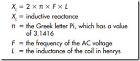
If these factors are known, a formula can be used to find the inductive reactance of the coil. This formula is:
EXAMPLE
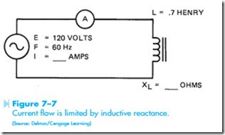
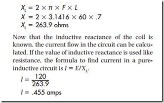
In the circuit shown in Figure 7–7, a coil has an inductance of .7 henrys, and is connected to a 120-volt, 60-Hz line. Find the current flow in the circuit.
To solve the problem, the first step is to find the amount of inductive reactance in the circuit.
VOLTAGE AND CURRENT RELATIONS
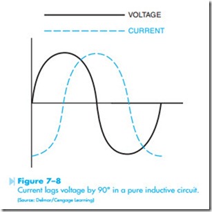
As stated previously, the voltage and current in a pure-resistive circuit are in phase with each other. In a pure-inductive circuit, however, the cur- rent lags behind the voltage by 90°, Figure 7–8.
In this type of circuit there is no true power or watts. In a resistive circuit, the resistor limits the cur- rent flow by converting the energy of the moving electrons into heat. This conversion of one form of energy into another represents a true power loss. In an inductive circuit, the energy of the moving electrons is stored in the magnetic field created around the inductor. When the magnetic field collapses, this energy is given back into the circuit. Notice that the resistor used the electrical energy by converting it into heat, but the inductor stored the energy and then returned it to the circuit.
IMPEDANCE
In an alternating-current circuit that contains only resistance, the current is limited by the value of the resistor only. In this type of circuit the current flow can be calculated using the Ohm’s law formula I = E/R.
In an AC circuit that contains only inductance, the current is limited only by the value of inductive reactance. In this type of circuit, the current flow can be calculated using the formula I = E/XL.
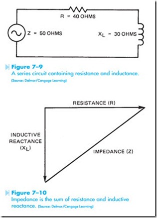
In a circuit like the one shown in Figure 7–9, there are elements of both resistance and inductive reactance contained in the same circuit. In this type of circuit, it cannot be said that the current is
Impedance is the sum of resistance and inductive reactance. (Source: Delmar/Cengage Learning)
limited by resistance, because there is also inductive reactance. It can also not be said that the current is limited by inductive reactance because of the resistance. Alternating-current circuits use a different value to represent the total amount of opposition to current flow in the circuit regard- less of what type of components are found in the circuit. This value is known as impedance and is given the symbol Z.
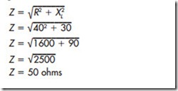
The resistor and inductor in Figure 7–9 are connected in series. Because these two components are connected in series, they will be added. They can- not be added in the normal way, however, because the inductance is not in phase with the resistance. Because inductive reactance is 90° out of phase with resistance, the total amount of opposition to current flow will be the value of the hypotenuse of the right triangle formed by the resistance and inductive reactance, Figure 7–10. To find the total value of impedance in this circuit, the formula Z = √R2 + X2 can be used. If the resistor has a value of 40 ohms and the inductor has an inductive reactance of 30 ohms, the impedance will be:
APPARENT POWER
In a direct-current circuit, the true power or watts is always equal to the voltage multiplied by the cur- rent because the current and voltage are never out of phase with each other. This also is true for an AC circuit that contains only pure resistance because the voltage and current are in phase.
In a circuit that contains pure inductance, how- ever, there is no true power or watts. In this type of circuit, the voltage multiplied by the current equals a value known as VARs, which stands for Volt-Amps Reactive. VARs is often referred to as wattless power.
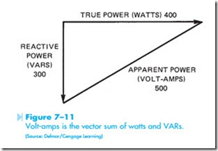
The apparent power or volt-amps of an AC circuit is the applied voltage multiplied by the current flow in the circuit. The amount of apparent power as compared to the true power or VARs is determined by the elements of the circuit itself. In the circuit shown in Figure 7–11, the amount of true
power is 400 watts. The amount of reactive power is 300 VARs. The apparent power is 500 volt-amps. Notice that the apparent power is found by adding the watts and VARs together in the same manner that the resistance and inductive reactance were added to find the total value of impedance. Volt-amps can be calculated by the formula:
POWER FACTOR
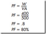
The power factor of an alternating-current circuit is a ratio of the apparent power compared to the true power. Power factor is important because utility companies charge industries large penalties for a poor power factor. The power factor of the circuit shown in Figure 7–11 can be found by:
Notice in this circuit, the power factor is 80%. This means 80% of the load is resistive and 20% is reactive. If the load is pure resistive, the power factor will be 100% or unity.
Utility companies become very concerned about power factor because they must furnish the amount of current needed to produce the volt-amp value. The company, however, is charged by the amount of true power or watts used. In this instance, if the applied voltage is 120 volts, the utility company must supply 4.16 amps to operate the load (500 volt-amps/120 volts = 4.16 amps). The actual amount of current being used to operate the load, however, is 3.33 amps (400 watts/120 volts = amps). Because the air conditioning load is often the major part of the electrical power consumed by an industry or office building, power factor can become an important consideration to the service technician.
