Stresses in turbine rotor blades
Although this chapter is primarily concerned with the fluid mechanics and thermodynamics of turbines, some consideration of stresses in rotor blades is needed as these can place restrictions on the allowable blade height and annulus flow area, particularly in high temperature, high stress situations. Only a very brief outline is attempted here of a very large subject, which is treated at much greater length by Horlock (1966), in texts dealing with the mechanics of solids, e.g., Den Hartog (1952) and Timoshenko (1956), and in specialized discourses, e.g., Japiske (1986) and Smith (1986). The stresses in turbine
blades arise from centrifugal loads, from gas bending loads, and from vibrational effects caused by non- constant gas loads. Although the centrifugal stress produces the biggest contribution to the total stress, the vibrational stress is very significant and thought to be responsible for fairly common vibratory fatigue failures (Smith, 1986). The direct and simple approach to blade vibration is to “tune” the blades so that resonance does not occur in the operating range of the turbine. This means obtaining a blade design in which none of its natural frequencies coincides with any excitation frequency. The subject is complex and interesting, but outside of the scope of the present text.
Centrifugal stresses
Consider a blade rotating about an axis O as shown in Figure 4.18. For an element of the blade of length dr at radius r, at a rotational speed Ω, the elementary centrifugal load dFc is given by
A rotor blade is usually tapered both in chord and in thickness from root to tip, such that the area ratio At/Ah is between 1/3 and 1/4. For such a blade taper, it is often assumed that the blade stress is reduced to two-thirds of the value obtained for an untapered blade. A blade stress taper factor can be defined as
Values of the taper factor K quoted by Emmert (1950) are shown in Figure 4.19 for various taper geometries.
Typical data for the allowable stresses of commonly used alloys are shown in Figure 4.20 for the “1000-h rupture life” limit with maximum stress allowed plotted as a function of blade tempera-ture. It can be seen that, in the temperature range 900-1100 K, nickel or cobalt alloys are likely to be suitable and for temperatures up to about 1300 K molybdenum alloys would be needed.
Further detailed information on one of the many alloys used for gas turbines blades is shown in Figure 4.21. This material is Inconel, a nickel-based alloy containing 13% chromium, 6% iron, with a little manganese, silicon, and copper. Figure 4.21 shows the influence of the “rupture life” and also the “percentage creep,” which is the elongation strain at the allowable stress and temperature of the blade. To enable operation at high temperatures and for long life of the blades, the creep strength criterion is the one usually applied by designers.
An estimate of the average rotor blade temperature Tb can be made using the approximation
EXAMPLE 4.5
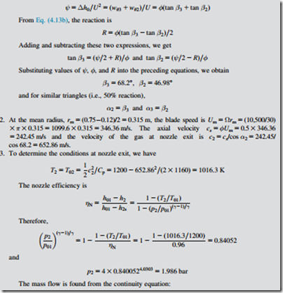
Combustion products enter the first stage of a gas turbine at a stagnation temperature and pressure of 1200 K and 4.0 bar. The rotor blade tip diameter is 0.75 m, the blade height is 0.12 m, and the shaft speed is 10,500 rev/min. At the mean radius the stage operates with a reaction of 50%, a flow coefficient of 0.7, and a stage loading coefficient of 2.5.
Assuming the combustion products are a perfect gas with γ 5 1.33 and R 5 287.8 kJ/kg K, determine:
1. the relative and absolute flow angles for the stage;
2. the velocity at nozzle exit;
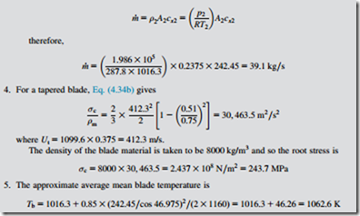
3. the static temperature and pressure at nozzle exit assuming a nozzle efficiency of 0.96 and the mass flow;
4. the rotor blade root stress assuming the blade is tapered with a stress taper factor K of 2/3 and the blade material density is 8000 kg/m2;
5. the approximate mean blade temperature;
6. taking only the centrifugal stress into account suggest a suitable alloy from the information provided that could be used to withstand 1000 h of operation.
Solution
1. The stage loading is
6. The data in Figure 4.20 suggest that, for this moderate root stress, cobalt or nickel alloys would not withstand a lifespan of 1000 h to rupture and the use of molybdenum would be necessary. However, it would be necessary to take account of bending and vibratory stresses and the decision about the choice of a suitable blade material would be decided on the out- come of these calculations.
Inspection of the data for Inconel 713 cast alloy, Figure 4.21, suggests that it might be a better choice of blade material as the temperature-stress point of the preceding calculation is to the left of the line marked creep strain of 0.2% in 1000 h. Again, account must be taken of the additional stresses due to bending and vibration.
Design is a process of trial and error; changes in the values of some of the parameters can lead to a more viable solution. In this case (with bending and vibrational stresses included), it might be necessary to reduce one or more of the values chosen, e.g., the rotational speed, the inlet stagnation temperature, and the flow area.
Note: The combination of values for ψ and φ at R 5 0.5 used in this example was selected from data given by Wilson (1987) and corresponds to an optimum total-to-total efficiency of 91.9%.


