Thermostatic Expansion Valves
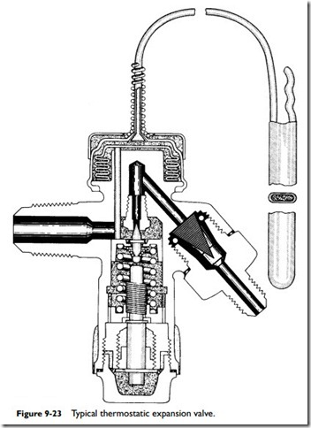
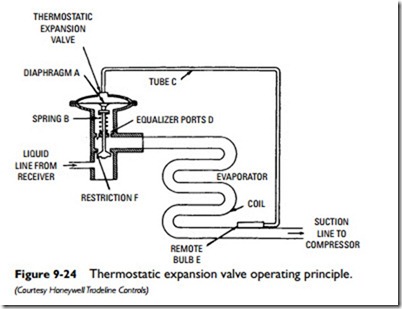
The thermostatic expansion valve is designed to automatically control the flow of liquid refrigerant entering the evaporator coil. The valve mechanism must operate freely and without restriction in order to allow the proper amount of refrigerant to enter the evaporator (see Figures 9-23 and 9-24).
Failure of any part of the thermostatic expansion valve will affect the refrigerating capacity of the unit and the cooling capacity of the system. Faulty operation of the expansion valve may be caused by mechanically frozen internal parts clogging the strainer or valve orifice, or by failure of the regulating sensor bulb, which operates the needle valve.
If the expansion valve is frozen partly open, the capacity of the unit will be affected because the flow of refrigerant is restricted. If the expansion valve is frozen in a fully open position, the liquid refrigerant may flow through the entire system, causing very cold inlet line, high inlet pressure, pounding of the compressor, and a cold compressor head.
The pressure in the sensor bulb or feeler of the expansion valve must be somewhat higher than the pressure in the evaporator, which means that the inlet line where the bulb is clamped must be at a higher temperature than that within the evaporator. Accordingly, the vapor in the inlet line at this point must be in a somewhat superheated state. This superheat should be at the minimum that will allow the valve to regulate the flow of refrigerant.
For higher-temperature work, such as comfort cooling work, the amount of superheating will vary between 5° and 10°. For lower- temperature work, such as product cooling work, the superheating will vary between 4° and 6° or in some cases even lower.
Excessive superheat indicates a lack of sufficient refrigerant flowing through the expansion valve, a condition that reduces the capacity of the evaporator.
The sensitivity and response of the thermostatic expansion valve is largely dependent on the proper installation of the sensor (feeler) bulb. The sensor bulb should always be firmly attached to the inlet line.
When properly installed and adjusted, the thermostatic expansion valve will maintain all the evaporator surface effective and in contact with the boiling refrigerant regardless of the change in load on the evaporator, provided of course that the evaporator valve has sufficient capacity for peak loads.
Under normal operating conditions, the sensor (feeler) bulb will cause the thermostatic expansion valve to close during the shut- down period. There are, however, certain conditions that will affect this and may cause overflooding of the evaporator. For this reason, the inlet lines should be trapped.
If the evaporator in an air-conditioning system is connected to outside air or where it may receive air at a temperature lower than that surrounding the sensor (feeler) bulb, the difference in temperature between the evaporator and the bulb will cause the valve to open and overflood the low side. Under such conditions, it is essential that the liquid line be equipped with a solenoid valve to positively shut off the refrigerant during the shutdown period.
Float Valves
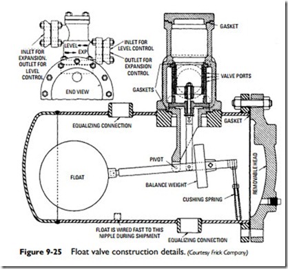
A float valve is one actuated by a float immersed in a liquid container (see Figure 9-25). Both low-side and high-side float valves are used to control the flow of liquid refrigerant in a refrigeration system.
A low-side float valve is one that is operated by a low-pressure liquid. It opens at a low level and closes when the liquid is at a high level. In other words, when there is no liquid in the evaporator, the float and lever arm are positioned so that the valve is left open. When liquid refrigerant under pressure from the compressor again enters the float chamber, the float rises until a predetermined level is reached and the valve is closed.
A high-side float valve is one that is operated by a high-side pressure. The valve opens on an increase of the liquid level in the float chamber and admits liquid to the low side.
Capillary Tubes
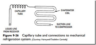
A capillary tube is a tube of small internal diameter used in refrigeration air-conditioning systems as an expansion device between the high-pressure and low-pressure sides. It can also be used to transmit pressure from the sensor bulb of some temperature controls to the operating element (see Figure 9-26).
The use of a capillary tube as a liquid refrigerant expansion device is largely limited to completely assembled factory refrigeration units because the bore diameters and the length of the tube are critical to its efficiency. The pressure reduction that occurs between the con- denser and evaporator results from the pressure drop or friction loss in the long, small-diameter passage provided by the capillary tube. No pressure-reducing valve is necessary between the high-side and low-side pressure zones when a capillary system is used.
Refrigerant Piping
The refrigerant travels between the various components of a mechanical refrigeration unit or system in small-diameter copper tubing sometimes referred to as the refrigerant lines.
The suction line is the piping between the evaporator and compressor inlet. Its function is to carry the refrigerant vapor to the compressor. It is important that the suction line be correctly sized for a practical pressure drop at full load. Under minimum load conditions, the suction line should be able to return oil from the evaporator to the compressor. Two other desirable features that should be incorporated in the design of a suction line are the following:
1. The prevention of oil drainage into a non-operating evaporator from an operating one.
2. The prevention of liquid drainage into a shut-down compressor.
The liquid line is the piping that carries the liquid refrigerant from the condenser or receiver to a pressure-reducing device.
The refrigerant piping (lines) should be carefully checked to make certain they will function properly. All connections should be examined for leaks, and all bends should be checked to make certain the tubing has not been squeezed together. A squeezed or pinched line will restrict the flow of refrigerant.
The slope of the suction line is also important in remote or split- system installations. When the evaporator coil is higher than the condensing unit, the suction line should be sloped with a continuous fall of at least 1⁄4 inch per foot toward the condensing unit.
If the evaporator coil is higher than the condensing unit and the excess line is coiled, the excess tubing must be coiled horizontally in such a way that the flow of refrigerant is from the top to the bot- tom of the coil and toward the condensing unit in a continuous fall (see Figure 9-27).
Related posts:
Incoming search terms:
- thermostatic expansion valve
- Capillary tube expansion valve
- Air Conditioning Equipment
- valves used in air conditioning
- tube connection of air condition
- thermostatic expansion valve function in air conditioning
- solenoid defrost
- installation thermostatic expansion valve
- hvac capillary tubes
- function of thermostatic valve in compressor
- float valve refrigeration
- expansion valve feeler bulb
- capillary tube refrigeration
- capillary tube of expansion valve
- capillary tube expansion device
- caida de presion en distribuidor de evaporador
- what is work of the expansion valve and solenoid valve in an air condition system


