Local Ventilation
Local ventilation is used to control atmospheric contamination or excessive heat at its source with a minimum of airflow and power consumption. It is not used to move a volume of air from one space to another for human comfort.
Air velocity is an important factor in local ventilation. Air must move fast enough past the contaminant source to capture fumes, grease, dust, paint spray, and other materials and carry them into an exhaust hood.
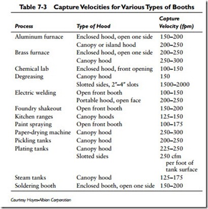
Both the capture velocity of the air at the contaminant source and the velocity at the discharge duct must be considered when designing a localized ventilation system. It is important to remember that capture velocities will differ depending on the contaminant. Table 7-3 lists the capture velocities for contaminants found in a variety of booths (that is, enclosures designed to isolate areas used for special purposes).
The selection of a suitable fan for a local ventilation system requires knowledge of the required fan cfm capacity and the static pressure (SP) at which the fan must work. Once these facts are known, you have all the necessary information required for sizing the fan from the manufacturer’s rating tables.
The required fan cfm capacity is determined by multiplying the open face area of any booth by the capture (face) velocity (fpm) of the air at the source of contamination.
The total open face area of any booth is determined by its physical size and the required access to the work area. If a booth is designed with several open face areas, all of them must be calculated and added together.
Capture (face) velocities (fpm) can be determined for various types of booths from data available from manufacturers and other sources. An example of such data is illustrated in Table 7-3.
The precise calculation of static pressure (SP) is not necessary for the sizing of a fan (or fans) in a local ventilation installation. An approximate calculation of static pressure will usually suffice, and the following steps are suggested for making such a calculation:
1. Assume the losses in the exhaust hood itself to be 0.05 inch to 0.10 inch SP.
2. Size the cross-sectional area of the main duct to ensure 1400- 2000 fpm velocity.
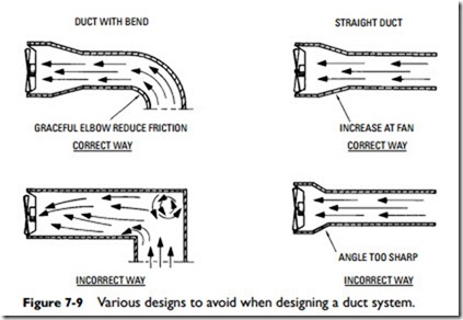
3. Keep all ductwork as short and straight as possible and avoid elbows and sharp turns (see Figure 7-9).
4. Determine the total straight duct length.
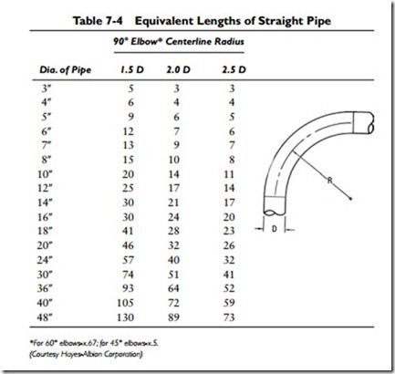
5. Add the equivalent straight duct length for each turn (see Table 7-4), and add it to step 4.
6. Multiply the sum of steps 4 and 5 by 0.0025 inch to deter- mine an approximate static pressure for the ductwork.
7. The static pressure for filters usually can be obtained from the filter manufacturer. If this is not possible, assume 0.25 inch SP for clean filters and 0.50 inch for dirty filters.
8. Add the static pressures from steps 1, 6, and 7 to obtain the approximate total static pressure for the installation.
9. Use the total static pressure for the installation and the required cfm capacity for sizing the fan.
Caution
Always check local building and safety codes for regulations pertaining to hazardous conditions. For extremely critical installations, such as those dealing with acids, poisons, or toxic fumes, consult the fan manufacturer for engineering analysis. It is strongly recommended that you do not attempt to make these calculations yourself. Finally, never undersize a fan. If you have any doubts about the correct size or horsepower, then select the next size larger.


