Performance measurement of wind turbines
Wind turbine performance relates to the energy availability in the wind at the turbines site. The wind can be described by a probability density distribution of turbulence of various frequencies superimposed on a momentarily steady component. The turbulent wind will have longitudinal, lateral, and vertical components of velocity. In this basic description of the wind, we will be concerned only with its longitudinal component c which will normally be parallel to the axis of rotation of the turbine. In the short term, the speed of the wind is to be considered as a steady component c and a fluctuating component .
Wind speed probability density function
From measurements of wind speeds at any one location and over a long enough period of time, it becomes apparent that the wind speed is more likely to be closer to a mean value than far from it. Also, the measured values will, in all probability, be as much above the mean as below it. The probability density function (p.d.f.) that best fits in with this type of erratic behavior of turbulence is called the Gaussian probability density distribution (or normal distribution).
The normal p.d.f. for continuously collected data is given by:
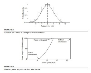
where![]() is the standard deviation and Ns is the number of readings taken over a time interval of (say) 10 s to determine the short-term wind speed, c 5 ð1 NsÞ PNs ci. = i51 Figure 10.5 shows a sample histogram of the wind speeds varying about a mean wind speed.
is the standard deviation and Ns is the number of readings taken over a time interval of (say) 10 s to determine the short-term wind speed, c 5 ð1 NsÞ PNs ci. = i51 Figure 10.5 shows a sample histogram of the wind speeds varying about a mean wind speed.
The Gaussian p.d.f. that represents this data is shown drawn onto this histogram.
Prediction of power output. The power output of a wind turbine is obviously a function of the wind speed. We will find that every wind turbine has its own characteristic power curve. From this curve, it is possible to predict the energy output without having to refer to more detailed information about the individual components of the turbine. Figure 10.6 shows the power output curve of a hypothetical wind turbine as a function of the wind speed at hub height.
There are three important key factors included in this diagram and which are applicable to all wind turbines. These are:
1. Cut-in wind speed: This is the minimum wind speed that the turbine can deliver useful power.
It is usually between 3 and 4 m/s.
2. Cut-out wind speed: This is the maximum wind speed that the turbine can safely deliver power.
This is a positive limit set by the stresses in the turbine components. If this limit is reached, the control system activates the braking system which brings the rotor to rest.
3. Rated output power and rated output wind speed: The electrical power output increases rapidly with wind speed. However, usually between 14 and 17 m/s, the maximum permitted power limit of the generator is reached. The rated output power and the corresponding wind speed is called the rated output wind speed. At higher wind speeds, the power output is kept constant by the control system making adjustment of the blade angles. The kinetic power available in the wind is
where A2 is the disc area and cx1 is the velocity upstream of the disc. The ideal power generated by the turbine can therefore be expected to vary as the cube of the wind speed. Figure 10.6 shows the idealized power curve for a wind turbine, where the preceding cubic “law” applies between the cut-in wind speed and the rated wind speed at which the maximum power is first reached. The rated wind speed often corresponds to the point at which the efficiency of energy conversion is close to its maximum.
Storing energy
Because of the intermittency of wind and the unavailability at times of the required energy, it is often claimed by opponents of wind turbines that it is better to rely on other sources of power. Clearly, some form of energy storage can be devised. For instance, in Spain more than 13.8 GW of wind power capacity has been installed, providing about 10% of that country’s electricity needs, according to Renewable Energy World (September-October, 2009). At Iberdrola, Spain, a pumped storage scheme (852 MW) is now being used to store the excess wind turbine energy and three further pumped storage plants are likely to be built with a total capacity of 1.64 GW.
In the following sections, the aerodynamic theory of the HAWT is gradually developed, starting with the simple 1D momentum analysis of the actuator disc and followed by the more detailed analysis of the blade element theory. The flow state just upstream of the rotor plane forms the so-called inflow condition for the rotor blades and from which the aerodynamic forces acting on the blades can be determined. The highly regarded blade element momentum (BEM) method2 is outlined and used extensively. A number of worked examples are included at each stage of development to illustrate the application of the theory. Detailed calculations using the BEM method were made to show the influence of various factors, such as the tip-speed ratio and blade number on performance. Further development of the theory includes the application of Prandtl’s tip loss correction factor, which corrects for a finite number of blades. Glauert’s optimization analysis is developed and used to determine the ideal blade shape for a given lift coefficient and to show how the optimum rotor power coefficient is influenced by the choice of tip-speed ratio.
Calculating the maximum possible power production of a wind turbine
This method of calculation, devised by Carlin (1997), is based on the Rayleigh probability energy distribution for a HAWT of a given size and determines the maximum possible average power for a given average wind speed c.
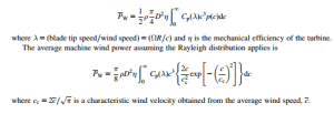
The average wind power produced by the turbine is given by:
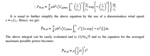
Some simplifications can now be made by assuming that the efficiency, η 5 1 and the power coefficient is replaced by the maximum value of the Betz coefficient, Cp;Betz 5 16=27. This form of the turbine power is the average idealized wind turbine power, PW;id
which may be worth remembering. You are reminded that this result is for an idealized wind turbine without losses, the value of Cp is assumed to be at the Betz limit and the wind speed probability is given by the Rayleigh distribution.
EXAMPLE 10.1
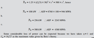
Determine the annual average energy production (AEP) of a 30 m diameter HAWT for a location at sea level with an annual average wind speed of (a) 6 m/s, (b) 8 m/s, (c) 10 m/s.
Assume that the air density is 1.25 kg/m3. Assume also that the efficiency is 100% and that Cp 5 0:5926 (the Betz maximum).
Solution


