Cable Reliability
Water Trees
The most common failure cause of solid-dielectric cables has been water treeing. Water trees develop over a period of many years and accelerate the failure of solid dielectric cables. Excessive treeing has led to the premature failure of many polyethylene cables. Cable insulation can tree two ways:
• Electrical trees — These hollow tubes develop from high electrical stress; this stress creates partial discharges that eat away at the insulation. Once initiated, electrical trees can grow fast, failing cable within hours or days.
• Water trees — Water trees are small discrete voids separated by insulation. Water trees develop slowly, growing over a period of months or years. Much less electrical stress is needed to cause water trees. Water trees actually look more like fans, blooms, or bushes whereas electrical trees look more like jagged branched trees. As its name indicates, water trees need moisture to grow; water that enters the dielectric accumulates in specific areas (noncrystalline regions) and causes localized degradation. Voids, contaminants, temperature, and voltage stress — all influence the rate of growth.
The formation of water trees does not necessarily mean the cable will fail. A water tree can even bridge the entire dielectric without immediate failure. Failure occurs when a water tree converts to an electrical tree. One explana- tion of the initiation of electrical trees is from charges trapped in the cable insulation. In Thue’s words (1999), “they can literally bore a tunnel from one void or contaminant to the next.” Impulses and dc voltage (in a hi-pot test) can trigger electrical treeing in a cable that is heavily water treed.
The growth rate of water trees tends to reduce with time; as trees fan out, the electrical stress on the tree reduces. Trees that grow from contaminants near the boundary of the conductor shield are most likely to keep growing. These are “vented” trees. Bow-tie trees (those that originate inside the cable) tend to grow to a critical length and then stop growing.
The electrical breakdown strength of aged cable has variation, a variation that has a skewed probability distribution. Weibull or lognormal distribu- tions are often used to characterize this probability and predict future failure probabilities.
Polyethylene insulation systems have been plagued by early failures caused by water trees. Early XLPE and especially HMWPE had increasing failure rates that have led utilities to replace large quantities of cable. By most accounts, polyethylene-based insulation systems have become much more resistant to water treeing and more reliable for many reasons (Dudas, 1994; EPRI 1001894, 2001; Thue, 1999):
• Extruded semiconducting shields — Rather than taped conductor and insulation shields, manufacturers extrude both semiconducting shields as they are extruding the insulation. This one-pass extrusion provides a continuous, smooth interface. The most dangerous water trees are those that initiate from imperfections at the interface between the insulation and the semiconducting shield. Reducing these imperfections reduces treeing.
• Cleaner insulation — AEIC specifications for the allowable number and size of contaminants and protrusions have steadily improved. Both XLPE compound manufacturers and cable manufacturers have reduced contaminants by improving their production and handling processes.
• Fewer voids — Dry curing reduces the number and size of voids in the cable. Steam-cured cables pass through a long vulcanizing tube filled with 205°C steam pressurized at 20 atm. Cables cured with steam have sizeable voids in the insulation. Instead of steam, dry curing uses nitrogen gas pressurized to 10 atm; an electrically heated tube radiates infrared energy that heats the cable. Dry curing has voids, but these voids have volumes 10 to 100 times less than with steam curing.
• Tree-retardant formulations — Tree-retardant formulations of XLPE perform much better in accelerated aging tests, tests of field-aged cables, and also in field experience.
EPR insulation has proven to be naturally water tree resistant; EPR cables have performed well in service since the 1970s. EPR insulation can and does have water trees, but they tend to be smaller. EPR cable systems have also improved by having cleaner insulation compounds, jackets, and extruded semiconductor shields.
Several accelerated aging tests have been devised to predict the performance of insulation systems. The tests use one of two main methods to quantify performance: (1) loss of insulation strength or (2) time to failure. In accelerated aging, testers normally submerge cables in water, operate the cables at a continuous overvoltage, and possibly subject the cables to thermal cycling. The accelerated water treeing test (AWTT) is a protocol that measures the loss of insulation strength of a set of samples during one year of testing (ANSI/ICEA S-94-649-2000, 2000). The wet aging as part of this test includes application of three times rated voltage and current sufficient to heat the water to 60°C. In another common test protocol, the accelerated cable life test (ACLT), cables are submerged in water, water is injected into the conductor strands, cables are operated to (commonly) four times nominal voltage, and cables are brought to 90°C for eight hours each day. The cables are operated to failure. Brown (1991) reported that under such a test, XLPE and TR-XLPE cables had geometric mean failure times of 53 and 161 days, respectively. Two EPR constructions did not fail after 597 days of testing. Because EPR and XLPE age differently depending on the type of stress, EPR can come out better or worse than TR-XLPE, depending on the test condi- tions. There is no consensus on the best accelerated-aging test. Normally such tests are used to compare two types of cable constructions. Bernstein concludes, “… there is still no acceptable means of relating service and laboratory aging to ‘remaining life’ ” (EPRI 1000273, 2000).
Even without voltage, XLPE cable left outdoors can age. EPRI found that XLPE cables left in the Texas sun for 10 years lost over 25% of their ac insulation strength (EPRI 1001389, 2002). These researchers speculate that heating from the sun led to a loss of peroxide decomposition by-products, which is known to result in loss of insulation strength.
Since water promotes water treeing, a few utilities use different forms of water blocking (Powers, 1993). Water trees grow faster when water enters the insulation from both sides: into the conductor strands and through the cable sheath. The most common water-protection method is a filled strand conductor; moisture movement or migration is minimized by the filling, which can be a semiconducting or an insulating filler. Another variation uses water absorbing powders; as the powder absorbs water it turns to a gel that blocks further water movement. An industry standard water block- ing test is provided (ICEA Publication T-31-610, 1994; ICEA Publication T- 34-664, 1996). In addition to reducing the growth and initiation of water trees, a strand-blocked conductor reduces corrosion of aluminum phase conductors. We can also use solid conductors to achieve the same effect (on smaller cables).
Another approach to dealing with water entry and treeing in existing cable is to use a silicone injection treatment (Nannery et al., 1989). After injection into the stranded conductor, the silicone diffuses out through the conductor shield and into the insulation. The silicone fills water-tree voids and reacts with water such that it dries the cable. This increases the dielectric strength and helps prevent further treeing and loss of life.
Another way to increase the reliability is to increase the insulation thick- ness. As an example, the maximum electrical stress in a cable with an insu- lation thickness of 220 mil (1 mil = 0.001 in. = 0.00254 cm) is 14% lower than a 175-mil cable (Mackevich, 1988).
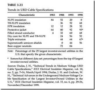
Utilities and manufacturers have taken steps to reduce the likelihood of cable degradation. Table 3.23 shows trends in cable specifications for under- ground residential cable. Tree-retardant insulation and smooth semiconductor shields, jackets and filled conductors, and dry curing and triple extrusion are features specified by utilities to improve reliability.
Good lightning protection also reduces cable faults. This requires surge arresters at the riser pole and possibly arresters at the cable open point (depending on the voltage). Keep arrester lead lengths as short as possible. Surges are a known cause of dielectric failures. Surges that do not fail the insulation may cause aging. Accelerated aging tests have found that 15-kV XLPE cables tested with periodic surges applied with magnitudes of 40, 70, and 120 kV failed more often and earlier than samples that were not surged (EPRI EL-6902, 1990; EPRI TR-108405-V1, 1997; Hartlein et al., 1989;
Hartlein et al., 1994). Very few of the failures occurred during the application of a surge; this follows industry observations that cables often fail after a thunderstorm, not during the storm.
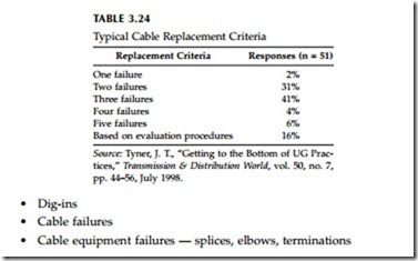
Rather than continue patching, many utilities regularly replace cable. Pro- gram policies are done based on the number of failures (the most common approach), cable inspection, customer complaints, or cable testing. High- molecular weight polyethylene and older XLPE are the most likely candi- dates for replacement. Most commonly, utilities replace cable after two or three electrical failures within a given time period (see Table 3.24).
Other Failure Modes
Cable faults can be caused by several events including:
Better public communications reduces dig-ins into cables. The most common way is with one phone number that can be used to coordinate marking of underground facilities before digging is done. Physical methods of reducing dig-ins include marker tape, surface markings, or concrete covers. Marker tape identifies cable. A few utilities use surface marking to permanently identify the location of underground facilities. Concrete covers above underground facilities physically block dig-ins.
Temporary faults are unusual in underground facilities. Faults are normally bolted, permanent short circuits. Reclosing will just do additional damage to the cable. Occasionally, animals or water will temporarily fault a piece of live-front equipment. Recurring temporary faults like these can be very difficult to find.
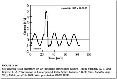
Another type of temporary, self-clearing fault can occur on a cable splice (Stringer and Kojovic, 2001). Figure 3.16 shows a typical waveform of an impending splice failure. This type of fault has some distinguishing charac- teristics: it self-clears in 1/4 cycle, the frequency of occurrence increases with time, and faults occur near the peak of the voltage. The author has observed this type of fault during monitoring (but never identified the culprit). This type of fault can occur in a cable splice following penetration of water into the splice. The water breaks down the insulation, then the arc energy melts the water and creates vapor at high pressure. Finally, the high-pressure vapor extinguishes the arc. The process can repeat when enough water accumulates again until the failure is permanent. This type of self-clearing fault can go unnoticed until it finally fails. The downside is that it causes a short-duration voltage sag that may affect sensitive equipment. Another problem, the fault may have enough current to blow a fuse; but since the fault self-clears, it can be much harder to find. Crews may just replace the fuse (successfully) and leave without replacing the damaged equipment.
Failure Statistics
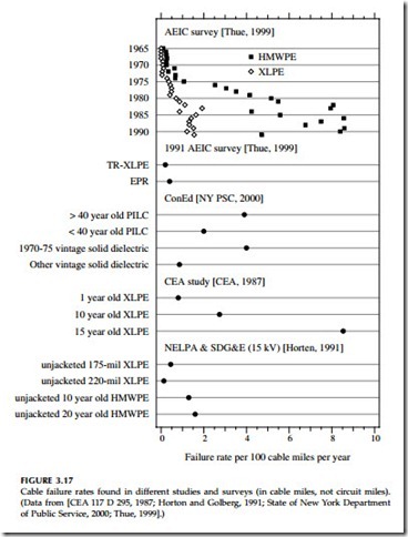
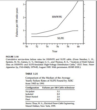
The annual failures of cables is on the order of 6 to 7 failures per 100 mi per year (3.7 to 4.3 failures per 100 km per year) according to survey data from the Association of Edison Illuminating Companies from 1965 through 1991 (Thue, 1999). Figure 3.17 shows cable failure data from a variety of sources; experience varies widely. Application, age, and type of cable markedly change the results. Utilities have experienced high failures of HMWPE, especially those that installed in the early 1970s. An EPRI database of 15 utilities showed a marked increase in failure rates for HMWPE cables with time (Stember et al., 1985). XLPE also shows a rise in failure rates with time, but not as dramatic (see Figure 3.18). The EPRI data showed failure rates increased faster with a higher voltage gradient on the dielectric for both HMWPE and XLPE.
Much of the failure data in Figure 3.17 is dominated by earlier polyethyl- ene-based cable insulation technologies. Not as much data is available on the most commonly used insulation materials: TR-XLPE and EPR. The AEIC survey reported results in 1991 — both had fewer than 0.5 failures per 100 cable mi during that year. TR-XLPE results were better (0.2 vs. 0.4 failures/ 100 mi/year for EPR), but the installed base of TR-XLPE would have been newer than EPR at that time. Jacketed cable has had fewer failures than unjacketed cable as shown in Table 3.25.
Another consideration for underground circuits is the performance of connectors and other cable accessories. 200-A elbows have failed at high rates (and they tend to fail when switching under load) (Champion, 1986).
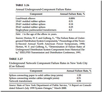
One important factor is that the type of splice should be correctly matched with the type of cable (Mackevich, 1988). Table 3.26 shows annual failure rates for some common underground components that were developed based on data from the Northwest Underground Distribution Committee of the Northwest Electric Light and Power Association (Horton and Golberg, 1990; Horton and Golberg, 1991). Table 3.27 shows failure rates of splices for New York City.
An EPRI review of separable connector reliability found mixed results (EPRI 1001732, 2002). Most utilities do not track these failures. One utility that did keep records found that failure rates of separable connectors ranged
from 0.1 to 0.4% annually. Of these failures, an estimated 3 to 20% are from overheating. They also suggested that thermal monitoring is a good practice, but effectiveness is limited because the monitoring is often done when the loadings and temperatures are well below their peak.
