Special Transformers
Autotransformers
An autotransformer is a winding on a core with a tap off the winding that provides voltage boost or buck. This is equivalent to a transformer with one winding in series with another (see Figure 4.21).
For small voltage changes, autotransformers are smaller and less costly than standard transformers. An autotransformer transfers much of the power directly through a wire connection. Most of the current passes through the lower-voltage series winding at the top, and considerably less current flows through the shunt winding.
Autotransformers have two main applications on distribution systems:
• Voltage regulators — A regulator is an autotransformer with adjust- able taps that is normally capable of adjusting the voltage by ±10%.
• Step banks — Autotransformers are often used instead of traditional transformers on step banks and even substation transformers where
the relative voltage change is moderate. This is normally voltage changes of less than a factor of three such as a 24.94Y/14.4 kV–12.47Y/7.2 kV bank.
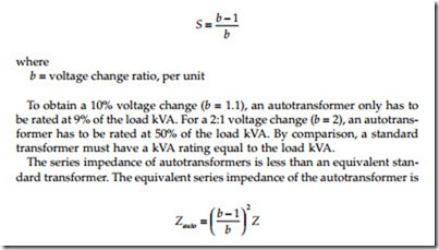
The required rating of an autotransformer depends on the voltage change between the primary and secondary. The rating of each winding as a per- centage of the load is
where Z is the impedance across the entire winding. A 5%, 100-kVA conven- tional transformer has an impedance of 25.9 W at 7.2 kV line to ground. A 2:1 autotransformer (b = 2) with a load-carrying capability of 100 kVA and a winding rating of 50 kVA and also a 5% winding impedance has an impedance of 6.5 W, one-fourth that of a conventional transformer.
For three-phase applications on grounded systems, autotransformers are often connected in a grounded wye. Other possibilities are delta (each wind- ing is phase to phase), open delta (same as a delta, but without one leg), and open wye. Because of the direct connection, it is not possible to provide ground isolation between the high- and low-voltage windings.
Grounding Transformers
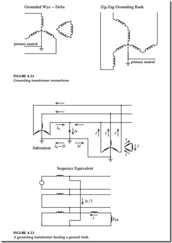
Grounding transformers are sometimes used on distribution systems. A grounding transformer provides a source for zero-sequence current. Grounding transformers are sometimes used to convert a three-wire, ungrounded circuit into a four-wire, grounded circuit. Figure 4.22 shows the two most common grounding transformers. The zig-zag connection is the most widely used grounding transformer. Figure 4.23 shows how a grounding bank supplies current to a ground fault. Grounding transformers
used as the only ground source to a distribution circuit should be in service whenever the three-phase power source is in service. If the grounding trans- former is lost, a line-to-ground causes high phase-to-neutral voltages on the unfaulted phases, and load unbalances can also cause neutral shifts and overvoltages.
A grounding transformer must handle the unbalanced load on the circuit as well as the duty during line-to-ground faults. If the circuit has minimal unbalance, then we can drastically reduce the rating of the transformer. It only has to be rated to carry short-duration (but high-magnitude) faults, normally a 10-sec or 1-min rating is used. We can also select the impedance of the grounding transformer to limit ground-fault currents.
Each leg of a grounding transformer carries one-third of the neutral current and has line-to-neutral voltage. So in a grounded wye – delta transformer, the total power rating including all three phases is the neutral current times the line-to-ground voltage:
ANSI/IEEE Std. 32-1972 requires a continuous rating of 3% for a 10-sec rated unit (which means the short-time rating is 33 times the continuous rating). A 1-min rated bank has a continuous current rating of 7%. On a 12.47-kV system supplying a ground-fault current of 6000 A, a zig-zag would need a 24.9-MVA rating. We will size the bank to handle the 24.9 MVA for 10 sec, which is equivalent to a 0.75-MVA continuous rating, so this bank could handle 180 A of neutral current continuously.
For both the zig-zag and the grounded wye – delta, the zero-sequence impedance equals the impedance between one transformer primary and its secondary.
Another application of grounding transformers is in cases of telephone interference due to current flow in the neutral/ground. By placing a ground- ing bank closer to the source of the neutral current, the grounding bank shifts some of the current from the neutral to the phase conductors to lower the neutral current that interferes with the telecommunication wires.
Grounding transformers are also used where utilities need a ground source during abnormal conditions. One such application is for a combination feeder that feeds secondary network loads and other non-network line-to- ground connected loads. If the network transformers are delta – grounded wye connected, the network will backfeed the circuit during a line-to-ground fault. If that happens while the main feeder breaker is open, the single-phase
load on the unfaulted phases will see an overvoltage because the circuit is being back fed through the network loads as an ungrounded system. A grounding bank installed on the feeder prevents the overvoltage during backfeed conditions. Another similar application is found when applying distributed generators. A grounded wye – delta transformer is often specified as the interconnection transformer to prevent overvoltages if the generator drives an island that is separated from the utility source.
Even if a grounding bank is not the only ground source, it must be sized to carry the voltage unbalance. The zero-sequence current drawn by a bank is the zero-sequence voltage divided by the zero-sequence impedance:
Severe voltage unbalance can result when one phase voltage is opened upstream (usually from a blown fuse or a tripped single-phase recloser). In this case, the zero-sequence voltage equals the line-to-neutral voltage. The grounding bank will try to hold up the voltage on the opened phase and supply all of the load on that phase, which could severely overload the transformer.


