Main features of construction
The core
The magnetic circuit in a transformer is built from sheets or laminations of electrical steel. Hysteresis loss is controlled by selecting a material with appropriate characteristics, often with large grain size. Eddy current loss is controlled by increasing the resistivity of the material using the silicon content, and by rolling it into a very thin sheet. The power loss characteristics of the available materials are shown in Fig. 6.5. Generally speaking the steels with lower power loss are more expensive, so that the 0.3 mm thick CGO steel shown is the cheapest of the range shown in Fig. 6.5, and the very low loss
mm thick Hi-B material with domain control techniques used to modify the apparent crystal size is the most expensive. New materials with thicknesses of 0.1 mm are available on a laboratory basis, but the use of such thin materials presents some production problems. A 25 µm thick amorphous ribbon can be used in very low loss transformers up to a few megavolt ampere and a core with losses of only one-sixth of the conventional 0.3 mm CGO material is possible. The general principles applying to electrical steels are discussed in Chapter 3.
The audible sound radiated by a transformer is generated by magnetostrictive deformation of the core and by electromagnetic forces in the windings, tank walls and magnetic shields. The dominant sound is generated by longitudinal vibrations in the core laminations, which are induced by the magnetic field. The amplitude of the vibrations depends upon the flux density in the core and on the magnetic properties of the core steel. In a large power transformer operating at high flux density, the audible sound level can exceed 100 dB(A) and it may be necessary to use high-quality core material, improved core-joint techniques and perhaps external cladding or a sound enclosure to reduce the sound to an acceptable level.
For many small transformers the cores are assembled using lamination stampings in C and I shapes and coils wound on to the bobbins from thin enameled wire are fitted to the core before closing the circuits.
In small power transformers, the core may take the form of a continuous strip of steel wound into a coil. The windings may be formed directly onto this core using toroidal winding machines, or the core may be cut to allow preformed windings to be fitted, and re-interlaced with the windings in place.
Where transformer weight is critical, it may be advantageous to operate a local power system at high frequency. Equation 6.3 relates voltage per turn to frequency and core cross section. If the transformer is to operate at 400 Hz (a typical requirement for aircraft), it can be seen that the core cross section will be only 12.5 per cent of that which would be necessary at 50 Hz. The clear advantage in cost and weight must be balanced against higher core losses at the increased frequency (although these can be reduced by using thinner laminations) and against higher load losses caused by high- frequency currents in the windings.
A longer established form of construction uses the stacked-core technique. For transformers which are rated in hundreds of watts the laminations may be stamped in E and I shapes, or in C and I shapes, then built into cores and assembled round the windings. At higher ratings in kilovolt ampere or megavolt ampere, the usual construction is to cut laminations to length, and to assemble them in a building berth which includes part of the core-clamping structure. When the core has been built, the remaining part of the clamping structure is fitted and the core is turned upright. If it has been fitted during the stacking stage, the top yoke is then removed, the windings are mounted on the core and the top yoke is then re-interlaced.
Single-phase transformers usually have a three-leg core with high-voltage and low-voltage windings mounted concentrically on the centre leg to reduce leakage flux and minimize the winding impedance. The outer legs form the return path for the magnetizing flux. This type of construction is shown in Fig. 6.6(a). For very high ratings in the region of 500 MVA, it may be economic to use a two-leg construction with two sets of windings connected in parallel and mounted one on each leg, as shown in Fig. 6.6(b). Where a transport height limit applies, a large single-phase transformer may be mounted on a four-leg core where the outer legs are used to return remnant flux, in conjunction with smaller top and bottom yokes. This arrangement is shown in Fig. 6.6(c).
Three-phase transformers are also based usually on a three-leg construction. In this case the high-voltage and low-voltage windings of each phase are mounted concentrically with one phase on each of the three legs. The phase fluxes sum to zero in the top and bottom yokes and no physical return path is necessary. This arrangement is shown in Fig. 6.6(d).
Where transport height is a limitation, a three-phase transformer may be built using a five-leg construction as shown in Fig. 6.6(e). The yoke areas in this case are reduced and the outer legs are included as return flux paths.
Core laminations are compacted and clamped together using yoke clamps connected by flitch plates on the outer faces of the legs, or by tie-bars locking the top and bottom yoke clamps together. Figure 6.7 shows a large three-phase, three-leg core in which the yokes are clamped by rectangular section steel frames and insulated straps; flitch plates lock the two clamps together and the core-bands on the legs are temporary, to be removed when the windings are fitted.
Windings
Winding conductors may be of copper or aluminium, and they may be in foil or sheet form, or of round or rectangular section. Foil or sheet conductors are insulated from each other by paper or Nomex interleaves, whereas round or rectangular conductors may be coated with enamel or wrapped with paper or some other solid insulation covering.
Low-voltage windings for transformers with ratings up to about 4 MVA may use foils with the full width of the winding, or round conductors. For higher-power trans- formers a large cross section may be necessary to carry the current in the low-voltage winding, and it may be economic to use stranded or parallel conductors in order to reduce eddy currents. It may also be necessary to transpose conductors during the winding operation to reduce circulating currents within the winding. For very high current applications, Continuously Transposed Conductor (CTC) may be used, where typically 40 or 50 conductors are machine transposed as shown in Fig. 6.8. In a CTC,
each strand is enamel insulated and the cable is enclosed in a paper covering. The conductors for low-voltage windings are usually wound in layers, with cooling ducts and interlayer insulation as part of the construction.
High-voltage windings have more turns and carry less current than the low-voltage windings. They are usually formed from round enamelled wire or paper-wrapped rectangular conductors. As with low-voltage windings, if the winding loss is to be minimized, parallel conductors or CTC may be used. The conductors are wound in layers or in discs, as shown in Figs. 6.9(a) and (b) respectively. The labour cost in a layer winding is high, and disc windings are usually considered to be more stable mechanically under the effects of through-current faults.
Many transformers have three or more windings. These may include regulating windings, tertiary windings to balance harmonic currents or supply auxiliary loads, multiple secondary windings to supply separate load circuits, or multiple primary circuits to connect to power supplies at different voltages or frequencies. The constructional aspects are common between multiple windings, but design aspects are more complicated.
Winding connections
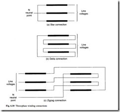
Three-phase transformers are usually operated with the high-voltage and low-voltage windings connected in Y (star), D (delta) or Z (zigzag) connection. The three styles are shown in Fig. 6.10.
In star connection, one end of each of the three-phase windings is joined together at a neutral point N and line voltage is applied at the other end; this is shown in Fig. 6.10(a). The advantages of star connection are:
• it is cheaper for a high-voltage winding
• the neutral point is available
• earthing is possible, either directly or through an impedance
• a reduced insulation level (graded insulation) is possible at the neutral
• winding tappings and tapchanger may be located at the neutral end of each phase, with low voltages to earth and between phases
• single-phase loading is possible, with a neutral current flowing
In delta connection, the ends of the three windings are connected across adjacent phases of the supply as shown in Fig. 6.10(b). The advantages of a delta connection are:
• it is cheaper for a high-current low-voltage winding
• in combination with a star winding, it reduces the zero-sequence impedance of that winding
A delta-connected tertiary winding is often used on large three-phase autotransformers to allow zero-phase sequence currents to circulate within the windings, or to allow triplen-frequency harmonic currents to flow in order to cancel out harmonic fluxes in the core.
The zigzag connection is used for special purposes where two windings are avail- able on each leg and are interconnected between phases as shown in Fig. 6.10(c). The advantages of a zigzag connection are:
• it permits neutral current loading with an inherently low zero-sequence impedance, and it is used in ‘earthing transformers’ to create an artificial neutral terminal on the system
• voltage imbalance is reduced in systems where the load is not evenly distributed between phases
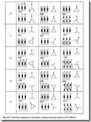
In order to define the range of possible connections, a designation has been adopted by IEC in which the letters Y, D, Z and N are assigned to the high-voltage windings and y, d, z and n are assigned to the low-voltage windings. Clock-hour designations 1 to 12 are used to signify in 30° steps the phase displacement between primary and secondary windings. Yy0 is the designation for a star–star connection where primary and secondary voltages are in phase. Yd1 is the designation for a star–delta connection with a 30° phase shift between primary and secondary voltages. The common connections for three-phase transformers are shown in Fig 6.11.
In many transmission transformers, an autotransformer connection is employed. The connection is shown in Fig. 6.12, and unlike the two-winding transformer in which primary and secondary are isolated, it involves a direct connection between two electrical systems. This connection can have a cost advantage where the ratio of input and output voltages is less than 5:1. Current flowing in the ‘series’ winding corresponds to that in the higher-voltage system only. The ‘common’ winding carries a current
which is the difference between the two systems, and being sized for this lower current it can be significantly cheaper. The autotransformer is more susceptible to damage from lightning impulse voltages and it has a lower strength against through- fault currents; both of these weaknesses can be corrected, but at increased cost.
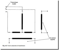
It may occasionally be necessary to make a three-phase to a two-phase transformation. This might be in order to supply an existing two-phase system from a new three-phase
system, or to supply a two-phase load (such as a furnace) from a three-phase system, or to supply a three-phase load (such as a motor) from a two-phase system. In all these cases the usual method of making the transformation is by using two single-phase transformers connected to each of the systems and to each other by the Scott connection shown in Fig. 6.13. On one transformer the turns ratio is equal to the transformation ratio, and the mid-point of the winding connected to the three-phase system is brought out for connection to the other single-phase transformer. The second transformer has a turns ratio of 0.866 times the transformation ratio. The primary winding is connected between the third phase of the three-phase supply and the mid- point of the primary winding of the first transformer. The secondary windings of the two transformers are connected to the two-phase supply (or load) using a three- or four-wire connection.
Bushings
Where transformers are enclosed within tanks to contain the insulating and cooling fluid, it is necessary to link the winding connections to the network using through- bushings which penetrate the tank.
Low-voltage bushings are generally solid. They are made of porcelain, ceramic or epoxy insulation with sufficient electrical strength to withstand abnormal voltages due to lightning activity or switching operations, and to withstand the service voltage over the lifetime of the transformer. Some low-voltage bushings carry high current and cooling is necessary. In such cases, it is usual to employ a hollow porcelain construction in which the internal connections are cooled by the oil in the tank.
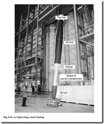
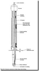
High-voltage bushings must withstand much higher voltage transients. They are usually of composite construction with a core of oil-impregnated or resin-bonded paper in an outer porcelain or epoxy cylinder. This outer cylinder is ‘shedded’ on the outside to increase its electrical strength under wet conditions. A typical high-voltage bushing with an oil-paper core is shown in Fig. 6.14(a); its internal construction detail is shown in Fig. 6.14(b).
Tapchangers
It has been explained in section 6.1 that when a transformer carries load current there is a variation in output voltage which is known as regulation. In order to compensate for this, additional turns are often made available so that the voltage ratio can be changed using a switch mechanism known as a tapchanger.
An off-circuit tapchanger can only be adjusted to switch additional turns in or out of circuit when the transformer is de-energized; it usually has between two and five tapping positions. An on-load tapchanger (OLTC) is designed to increase or decrease the voltage ratio when the load current is flowing, and the OLTC should switch the
transformer load current from the tapping in operation to the neighbouring tapping without interruption. The voltage between tapping positions (the step voltage) is normally between 0.8 per cent and 2.5 per cent of the rated voltage of the transformer.
The OLTC mechanisms are based either on a slow-motion reactor principle or a high-speed resistor principle. The former is commonly used in North America on the low-voltage winding, and the latter is normally used in Europe on the high-voltage winding.
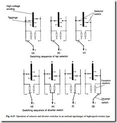
The usual design of an OLTC in Europe employs a selector mechanism to make connection to the winding tapping contacts and a diverter mechanism to control cur- rent flows while the tapchanging takes place. The selector and diverter mechanisms may be combined or separate, depending upon the power rating. In an OLTC which comprises a diverter switch and a tap selector, the tapchange occurs in two operations. First, the next tap is selected by the tap switch but does not carry load current, then the
diverter switches the load current from the tap in operation to the selected tap. The two operations are shown in seven stages in Fig. 6.15.
The tap selector operates by gearing directly from a motor drive, and at the same time a spring accumulator is tensioned. This spring operates the diverter switch in a very short time (40 – 60 ms in modern designs), independently of the motion of the motor drive. The gearing ensures that the diverter switch operation always occurs after the tap selection has been completed. During the diverter switch operation shown in Fig. 6.15(d), (e) and (f), transition resistors are inserted; these are loaded for 20 –30 ms and since they have only a short-time loading the amount of material required is very low.
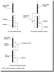
The basic arrangement of tapping windings is shown in Fig. 6.16. The linear arrangement in Fig. 6.16(a) is generally used on power transformers with moderate regulating ranges up to 20 per cent. The reversing changeover selector shown in Fig. 6.16(b) enables the voltage of the tapped winding to be added or subtracted from the main winding so that the tapping range may be doubled or the number of taps reduced. The greatest copper losses occur at the position with the minimum number of effective turns.
This reversing operation is achieved with a changeover selector which is part of the tap selector of the OLTC. The two-part coarse–fine arrangement shown in Fig. 6.16(c) may also be used. In this case the reversing changeover selector for the fine winding can be connected to the ‘plus’ or ‘minus’ tapping of the coarse winding, and the cop- per losses are lowest at the position of the lowest number of effective turns. The coarse changeover switch is part of the OLTC.
Regulation is mostly carried out at the neutral point in star windings, resulting in a simple, low-cost, compact OLTC and tapping windings with low insulation strength to earth. Regulation of delta windings requires a three-phase OLTC, in which the three phases are insulated for the highest system voltage which appears between them; alternatively three single-phase OLTCs may be used.
Cooling equipment
Transformers may be naturally cooled, in which case the cooling medium (oil or air) circulates by thermosyphon forces, or they may be forced cooled, with fans or pumps to circulate the air or oil over the core and through the windings.
In oil-cooled transformers a more economic solution is to use directed oil-flow cooling in which oil is pumped directly into the windings. The oil is cooled by passing (or pumping) it through plate radiators, which may be externally cooled by fans, or by using forced air-cooled tubular construction, or by pumping it through watercoolers. Designations for these cooling systems which identify both the cooling fluid and the type of cooling have been assigned by IEC and these are summarized in Table 6.1.


