Instrument Transformers Calibration
As part of the relay testing and calibration, instrument transformers, such as CT, VT, and capacitive potential devices, should be given excitation, ratio, polarity, and continuity checks. These tests are discussed in detail in Section 9.2 however a brief overview of these tests is as follows:
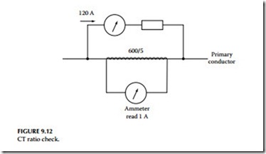
Ratio check—CTs
The connections for the ratio check test are shown in Figure 9.12. Apply current to the primary to give 1 A in the secondary. For example, in the connection diagram, 120 A is applied to the primary of a 600/5 CT. For a correct ratio check, 1 A should be measured by the ammeter connected in the CT secondary circuit.
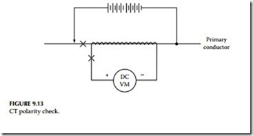
Polarity check
The connection diagram for polarity check is shown in Figure 9.13. The negative side of the 7.5 V battery is connected to the nonpolarity side of the CT. Connect a DC voltmeter or low-reading ammeter in the secondary of the CT; the positive side of the battery terminal is left unconnected. To verify polarity connections, momentarily touch the battery positive terminal as shown in the diagram.
If the meter needle deflects in the positive direction, polarity is true as connected. If the meter needle deflects in the negative direction, then polarity connections are not as shown connected.
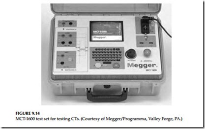
The tests for CTs discussed above may be conducted using a CT test sets made by Megger Limited. These test sets are model CTER-91 and MCT-1600 which are very portable, and use the voltage comparison method for testing CTs. Both of these models can be used to test single and multiratio CTs in accordance with IEEE Standard C57.13.1 using a variable voltage source and precision instrumentation.
These test sets can automatically perform saturation, ratio, and polarity tests all at the same time and display results, including saturation curves on a graph- ical display. Test results can also be printed directly or stored in an electronic file for future comparison or trending purposes. The MCT-1600 is a newer test set which can produce up to 1A at 1600 V and up to 5A at 40 V. This allows satu- ration testing of most large bushing CTs and burden testing of external CT load circuits. Multiratio CTs should be tested on the individual taps to verify specific saturation and ratio settings applicable to desired relaying schemes.
All of the three tests discussed above, saturation, ratio, and polarity, can be performed without changing any leads. The advantage of using these test sets is that CTs may be tested in their equipment configuration, such as
mounted in transformers, oil circuit breakers, or switchgear. This eliminates the need to remove bushings or remove CTs from their mounting. Of course, it is necessary for the equipment to be deenergized and totally isolated from the electrical system prior to making these tests. The MCT-1600 model is shown in Figure 9.14.
Grounding CT and VT circuits
The CT and VT circuits should be grounded at only one point. Relay misoperations can be caused by grounding the neutral at two points, such as one ground at the switchyard and another at the relay panel. At least once every 3 years with the primary de-energized, the known ground should be removed and the overall circuits should be checked for additional grounds and insulation breakdowns.
Open-secondary sircuits
WARNING: Secondary circuits of CTs must not be open while primary cur- rent flows. Extreme care should be taken to avoid breaking the secondary circuit while primary current is flowing. If the secondary is open-circuited, the primary current raises core flux density to saturation and induces a high voltage pulse in the secondary every half cycle. This high voltage pulse can be four to six times normal voltage and can endanger human life, and damage connected apparatus and leads. If it is necessary to change secondary condi- tions while primary current is flowing, the secondary terminals must be short-circuited while the change is being made. Caution should be exercised when working with differential circuits as shorting a CT in an energized dif- ferential relaying circuit could result in a relay operation. It is recommended that the secondaries of all CTs be kept short-circuited at all times when not installed in a circuit such as being held in stock or being transported.
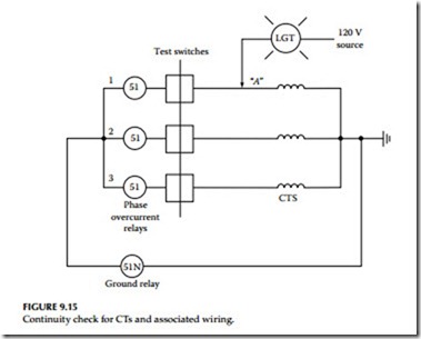
Continuity check (backfeed test)
This test is conducted to check the CT windings and the wiring from test switch to CT (backfeed) for the three phases. The relay test connection diagram is shown in Figure 9.15. Conduct tests as follows:
• Apply 120 V low current (about 3 A) or a 20 V source with a 100 W lamp at point A. Point A is the test switch location where the protec- tive relay is isolated from CTs with the relay ground maintained. If the lamp has no glow or no current reading is observed, the CT windings are checked.
• Next, jumper to ground the hot side of the CT. The lamp will glow brightly (or 3 A will read on low-ampere source). This indicates that relay circuit wiring is continuous without any shorts or open.
• Measure the insulation resistance of transformer secondary windings and CT leads with a 500 V megohmmeter.
• Measure the transformer primary insulation with applicable potential test apparatus.
• Repeat the preceding test to check all three phases.
• Verify the connection of the secondary VT leads by applying a low volt- age to the leads and checking for this voltage at applicable devices.
• Check for a VT secondary load with secondary voltage and cur- rent measurements. Make sure that the load is less than the rating of the VT.


