Medium-voltage (distribution) switchgear
Distribution switchgear, also commonly referred to as medium-voltage switchgear, is generally acknowledged to cover the range 1 kV to 36 kV; 72.5 kV and even 132 kV can be considered as distribution voltages rather than transmission voltages, and the equipment overlaps with high-voltage or transmission switchgear in this range.
Switchgear in the distribution voltage range differs considerably from low-voltage switchgear. There are similarities with aspects of transmission switchgear, but many functions and practices are different.
Types of circuit breaker
In the past, oil- and air-break devices have predominated, but now several alternative methods of arc interruption are used in distribution-voltage circuit breakers.
Early oil designs featured plain-break contacts in a tank of oil capable of withstanding the considerable pressure built up from large quantities of gas generated by long arcs. During the 1920s and 1930s various designs of arc control device were introduced to improve performance. These were designed such that the arc created
between the contacts produces enough energy to break down the oil molecules, generating gases and vapours which by the cooling and de-ionizing of the arc resulted in successful clearance at current zero. During interruption, the arc control device encloses the contacts, the arc, a gas bubble and oil. Carefully designed vents allow the gas to escape as the arc is lengthened and cooled. Figure 7.13 shows an axial-blast arc control device. The use of oil switchgear is reducing significantly in most areas of the world because of the need for regular maintenance and the risk of fire in the event of failure.
Sulphur hexafluoride (SF6) is the most effective gas for the provision of insulation and arc interruption. It was initially introduced and used predominantly in transmission switchgear, but it became popular at distribution voltages from the late 1970s.
The main early types of SF6 circuit breaker are known as ‘puffer’ types. These use a piston and cylinder arrangement, driven by an operating mechanism. On opening, the cylinder containing SF6 gas is compressed against the piston, increasing the gas pressure; this forces the gas through an annular nozzle in the contact giving a ‘puff’ of gas in the arc area. The gas helps to cool and de-ionize the arc, resulting in arc interruption at current zero. The dielectric properties of SF6 are quickly re-established
in the heat of the arc, giving a rapid increase in dielectric strength as the voltage across the contacts begins to rise. The energy required to drive the puffer type of circuit breaker is relatively high, resulting in the need for a powerful mechanism.
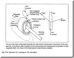
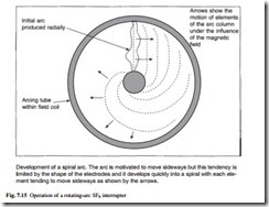
Other designs of SF6 circuit breaker started to be introduced in the 1980s. These make more use of the arc energy to aid interruption, allowing the use of a lighter and cheaper operating mechanism. Whilst in the puffer design the compressed SF6 is made to flow over an arc which is basically stationary, these newer designs move the arc through the SF6 to aid interruption. In the rotating arc SF6 circuit breaker, a coil is wound around the fixed contact. As the moving contact withdraws from the fixed contact the current is transferred to an arcing contact and passes through the coil. The current in the coil sets up an axial magnetic field with the arc path at right angles to the magnetic flux, and rotation of the arc is induced according to Fleming’s left-hand rule (see Chapter 2, eqn 2.16). The arc rotation is proportional to the magnitude of the current. Careful design is required in order to ensure an adequate phase shift between the flux and the current to maintain adequate movement of the arc as the current falls towards its zero crossing. The operation of a rotating-arc interrupter is illustrated in Figs 7.14 and 7.15.
Other types of self-extinguishing circuit breaker use an insulating nozzle which is similar to that in a puffer breaker, but with a coil to produce a magnetic field for moving the arc. The thermal energy in the arc is used to increase the local pressure. This results in arc movement which again is proportional to the current, and successful interruption follows. In some designs a small puffer is also used to ensure there is enough gas flow to interrupt low levels of current, where the thermal energy in the arc is relatively low.
The various types of SF6 switchgear are referred to with respect to high-voltage switchgear in section 7.5.2, and Fig. 7.24 shows the main configurations.
The main alternative to the SF6 circuit breaker in the medium-voltage range is the vacuum interrupter. This is a simple device, comprising only a fixed and a moving contact located in a vacuum vessel, but it has proved by far the most difficult to develop. Although early work started in the 1920s, it was not until the 1960s that the first vacuum interrupters capable of breaking large currents were developed, and commercial circuit breakers followed about a decade later.
The principle of operation of a vacuum interrupter is that the arc is not supported by an ionized gas, but is a metallic vapour caused by vaporization of some of the contact metal. At zero current, the collapse of ionization and vapour condensation is very fast, and the extremely high rate of recovery of dielectric strength in the vacuum ensures a very effective interrupting performance. The features of a vacuum interrupter which are key to its performance are the contact material, the contact geometry and ensuring that the envelope (a glass or ceramic tube with welded steel ends) remains vacuum-tight throughout a working life in excess of 20 years. Even today, specialized manufacturing techniques are necessary to achieve this. A typical vacuum interrupter is shown in Fig. 7.16.
The circuit breaker is located within a switchgear housing, some types of which are described later. The main insulation in the housing is usually air, although some designs now have totally sealed units filled with SF6 gas. Structural isolation is required to support current-carrying conductors; this is normally some type of cast resin. Thermoplastic materials which can be injection-moulded are often used for smaller components, but larger items such as bushings which are insulation-covered are usually made from thermosetting materials such as polyurethane or epoxy resin mixed with filler to improve its mechanical and dielectric properties.
Main classes of equipment
Primary switchgear
Primary substations up to 36 kV are usually indoor, although they can be outdoor where space is not a problem. Indoor equipment is usually metal-enclosed, and it can be subdivided into metalclad, compartmented and cubicle types. In the metalclad type, the main switching device, the busbar section and cable terminations are segregated by metal partitions. In compartmented types the components are housed in separate compartments but the partitions are non-metallic. The third category covers any form of metal-enclosed switchgear other than the two described.
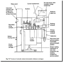
The vertically isolated, horizontally withdrawn circuit breaker is the traditional arrangement in the UK or UK-influenced areas. This originates from the bulk-oil circuit breaker, for which there was a need for easy removal for frequent maintenance, but manufacturers have utilized the already available housings to offer vacuum or SF6 circuit breakers as replacements for oil circuit breakers, or even for new types to this design. The design also provides convenient earthing of the circuit or busbars by alter- native positions of the circuit breaker in the housing; this is achieved by disconnecting the circuit breaker, lowering it from its service position, moving it horizontally and then raising and reconnecting the connections between the busbar or cable and earth. A typical section is shown in Fig. 7.17.
Horizontally isolated, horizontally withdrawn equipment has been used extensively in mainland Europe, with air-break, small oil volume and latterly with SF6 and vacuum circuit breaker truck designs. A section of this type of switchgear is shown in Fig. 7.18. Since the circuit breaker cannot be used as the earthing device in this design, integral earthing switches or portable earthing devices are required.
Fixed-position circuit breakers were introduced in the 1970s; these depart from the withdrawable arrangements and are based on a ‘sealed-for-life’ concept. Due to the early problems with vacuum interrupters, some users were reluctant to accept fixed-position vacuum switchgear, but now that excellent long-term reliability of vacuum interrupters has been established, newer designs have been introduced again recently. Several arrangements in which the housing is completely sealed and filled with SF6 as a dielectric medium are now available and an example is shown in Fig. 7.19. Because of the compact dimensions that SF6 permits these are gaining popularity, particularly at 36 kV, where there can be a cost advantage not only in the price, but also in the reduced size of the equipment and the substation required.
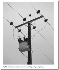
Most faults on overhead systems are caused by lightning strikes, branches brushing the conductors, clashing of conductors in high wind, or large birds bridging the lines; they are usually transient in nature. In most cases the fault duration is short and the circuit breakers used in these circuits, known as reclosers, are programmed to close again a very short time after they have opened. This allows the fault to be cleared with a minimum of disruption to consumers. It is normal to programme the recloser to open, then close up to four times in order to allow time for the fault to disappear. If after this time the fault is still present, it is assumed that the fault is not transient; the recloser then locks out and the faulty section of the line is isolated. A recloser normally controls sev- eral circuits. An 11 kV pole-mounted auto-recloser is shown in Fig. 7.20. Reclosers are available with SF6 and vacuum interrupters; the equipment used in conjunction with reclosers are switches and sectionalizers, which can be air-break switches, vacuum or SF6 devices expulsion fuses and off-load switching devices.
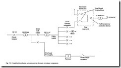
Most urban areas in UK and Europe are supplied by underground cable. In this case the step-down transformer (for example 11 000/415 V) which supplies a consumer circuit is connected to a protective device such as a fuse switch or circuit breaker in a ring. A simplified distribution network with the main components is shown in Fig. 7.21. The ‘ring main unit’ usually has two load-break switches with the control protective device combined into a single unit. In UK this type of unit is ruggedly designed for outdoor use, but in continental Europe indoor designs are more normal. The traditional oil-filled unit has been replaced largely by SF6 equipment over recent years. The ring main unit has normally been manually operated with a spring-operated mechanism to ensure that their operation is not dependent on the force applied by the operator. However, as utilities press to improve the reliability of supplies to consumers and to reduce the time lost through outages caused by faults, the use of automatically operated motor-driven spring mechanisms is now on the increase.
Rating principles
The main consideration in the choice of switchgear for a particular system voltage is the current it is capable of carrying continuously without overheating (the rated normal current) and the maximum current it can withstand, interrupt and make onto under fault conditions (the rated short-circuit current). Studies and calculations based on the circuits of interest will quantify these parameters. The switchgear rating can then be chosen from tables of preferred ratings in the appropriate standard, such as IEC 694 and IEC 56. Table 7.4 shows figures taken from IEC 56 showing the co-ordination of rated values for circuit breakers. Ratings vary commonly from less than 400 A in a secondary system to 2000 A or more in a primary substation, with fault currents of 6 kA in some overhead line systems up to 40 kA and above in some primary circuits.
The standards also specify overvoltages and impulse voltages which the switchgear must withstand. Normal overvoltages which occur during switching or which may be transferred due to lightning striking exposed circuits must be withstood. The switchgear also needs to provide sufficient isolating distances to allow personnel to work safely on a part of the system that has been disconnected. The lightning impulse withstand voltage and the normal power frequency withstand voltage are specified relative to the normal system voltage in the standards.
Test methods
Type tests are performed on a single unit of the particular type and rating in question. They are performed to demonstrate that the equipment is capable of performing the
rated switching and withstand duties without damage, and that it will provide a satisfactory service life within the limits of specified maintenance. The main type tests are as follows:
● dielectric tests. Lightning impulse is simulated using a standard waveshape having a very fast rise time of 1.2 µs and a fall to half value of 50 µs. Power frequency tests are performed at 50 Hz or 60 Hz. The method of performing the tests is detailed in standards, for instance IEC 60, ‘Guide to high voltage testing techniques’. This requires the switchgear to be arranged as it would be in service. If outdoor-rated, the tests need to be carried out in dry and wet conditions,
the latter using water of specified conductivity which is sprayed onto the equipment at a controlled rate during application of the high voltage.
● temperature rise tests. Again the switchgear is arranged in its service condition, and the normal continuous current is applied until the temperature of the main components has stabilized. The final temperature, measured by thermocouples, must not exceed values stated in the specifications; these values have been chosen to ensure that no deterioration of metal or insulation is caused by continuous operation.
● short circuit and switching tests. These are conducted over a range of currents from 10 per cent to 100 per cent of the short circuit rating. The tests are at low power factor, which represents the most onerous switching conditions seen in service.
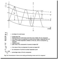
The different levels represent short circuits at various points in the system, from close to the circuit breaker terminals to a long distance along the cable or line. Whilst the current to interrupt varies with these positions, another major factor is the rate of rise of the transient recovery voltage appearing across the circuit breaker contacts; this can have a significant influence on the circuit breaker performance and it plays a key part in the design. The ability to interrupt the short- circuit current with a decaying dc component superimposed on the power frequency must also be demonstrated. The decrement or rate of decay of the dc voltage is specified in the standards, but the dc component which is present when the contacts open depends upon the opening time of the circuit breaker (it being reduced if the opening time is long). Figure 7.22 shows the determination of short-circuit making and breaking currents and of the dc component. Circuit breakers must also be tested when closing onto a fault condition,
and then carrying the full short-circuit current for a specified period, usually one or three seconds.
● mechanical endurance test. To demonstrate that the equipment has a satisfactory life, this test is performed over a specified number of operations which depends upon the type of equipment and duty; the number of open–close operations can vary from 1000 to 10 000. The tests are carried out without electrical load, but at the rated output of the mechanism of the device.
Routine tests are performed by the manufacturer on every unit of switchgear to ensure that the construction is satisfactory and that the operating parameters are similar to the unit which was subjected to the type test. These tests are specified in the standards, and the minimum performed will include the following:
● power frequency voltage withstand dry tests on the main circuit
● voltage tests on the control and auxiliary circuits
● measurement of the resistance of the main circuit
● mechanical operating tests
Commissioning and maintenance
Switchgear is usually transported in sections which need to be carefully erected and connected together at the substation.
Commissioning tests are performed after installation; these are necessary to ensure that the connections are sound and that the equipment is functioning satisfactorily. These tests will normally include checks of current and voltage transformers, checking of the protection scheme, circuit breaker operation and high-voltage withstand tests.
With the demise of oil-filled switchgear the requirement for maintenance has been significantly reduced. SF6 and vacuum circuit breakers which are ‘sealed for life’ should require no servicing of the interrupting device. Manufacturers provide instructions on simple inspection and servicing of other parts of the circuit breaker; this is usually limited to cleaning, adjustment and lubrication of the mechanism.
Standards
Some of the commonly used standards and specifications for distribution switchgear are given in Table 7.5.


