Simulation Results
Network percolation can be implemented in many ways. In this chapter, we have implemented a method which is computationally efficient making it applicable for on line processing of information while cascade in progress. The process of per- colation can be implemented as follows:
1. Consider an empty network.
2. Initialize c ¼ 0, where c represents the number of cluster in the network.
3. Choose the order of addition of vertices in the empty network.
4. According to the order add next vertex to the network, and increase c by one.
5. Label the vertex with label c. This number represents the cluster of the vertex.
6. Investigate edges attached to the vertex one after another.
7. If the vertex at the other end of the edge has been added earlier, add the edge to the network.
8. Examine the cluster label of the vertices at either end of the edge.
9. If the cluster labels are the same, do nothing.
10. If the labels are different, choose one of the clusters and re-label all its vertices to have the same label as the other cluster.
11. Update the cluster size record to be equal to the sum of the sizes of the two parent clusters.
12. Repeat from step 4, until all the vertices have been added.
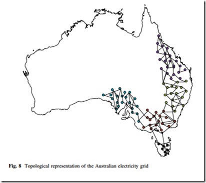
The test systems used for the percolation analysis are standard IEEE test systems [22] and the Australian power grid [23]. Figure 8 is the topological representation of the Australian power grid. The Australian power grid operated under the National Electricity Market (NEM) is the world’s longest interconnected
power system that runs for more than 5,000 km from Port Douglas in Queensland to Port Lincoln in South Australia and supplies more than 10 billion electricity annually to meet the demand of more than 8 million end users [23]. NEM inter- connects five regional market jurisdictions including Queensland, New South Wales, Victoria, South Australia, and Tasmania.
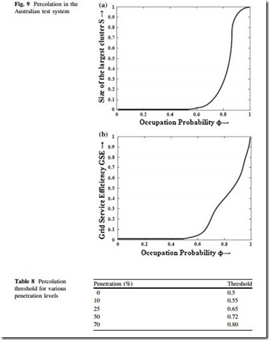
Figure 9 is the result of percolation process carried out in the Australian test system, with random node and line removal. The results shown are averaged over 1,000 random simulations. It is clear from the result that GSE is a good measure of network robustness, since although the network seems to breaks down around / ¼ 0:6 in case of largest cluster-based analysis; but the network can perform well beyond that point since the percolation threshold is around / ¼ 0:5 as shown in Fig. 8.
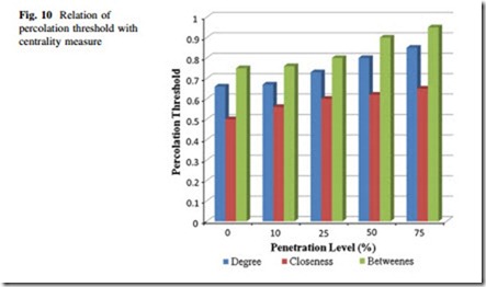
Next, the penetration levels of renewable are varied for the Australian test system and percolation thresholds are calculated. It is found that, as given in Table 8, the threshold increases with increase of penetration, which implies increased vulnerability of the power grid with large-scale penetration of excess energy in the existing grid. Afterwards, nodes and edges are removed from the system according to various centrality measures, and it is found that network is
hampered much is betweenness-based attacks are carried out on the system. This result, shown in Fig. 10, gives us an opportunity to allocate our resources to regularly monitor and service critical elements.
