Effect of Reactive Power in Case of Single Converter
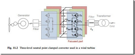
As the most commercialized multilevel topology which is widely used in the high-power medium-voltage drives for industry, mining, and traction applications, the three-level neutral-point-clamped (3L-NPC) converter seems to be a promising candidate for the Multi-MW full-scale wind power conversion system, as shown in Fig. 11.2. This converter is chosen and basically designed based on a 10 MW wind turbine as a case study, where the major design parameters are summarized in Table 11.1.
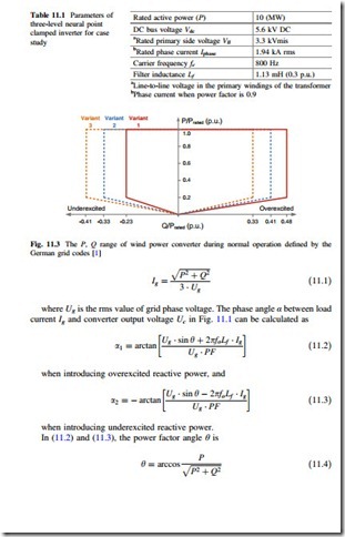
For a single wind power generation system, the maximum reactive power achieved by the grid side inverter has to be restrained in a certain range according to the grid standards [1–3], as shown in Fig. 11.3, in which the allowable boundaries of reactive power with relation to the generating active power is defined by German grid code when the grid voltage is within ±5 % range around nominal value. It can be seen that in the definition of Variant 1 the overexcited reactive power Q+ should be less than 48 % of the rated active power Prated, and the underexcited reactive power Q− should be less than 23 % of Prated.
Referring to the phasor diagram of the grid side converter in Fig. 11.1, the mplitude of the load current Ig in relation to the reactive power Q and active power P can be calculated as
given the condition that the power factor are maintained and generating active power P is larger than 20 % of its rated value.
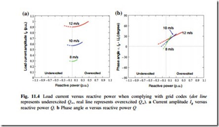
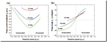
Then the amplitude and phase angle of the load current Ig in relation to the reactive power p.u. can be plotted in Fig. 11.4a, b respectively, in which the situations when the wind speed is 12 m/s (P = 10 MW, 1 p.u.), 10 m/s (P = 6.3 MW, 0.63 p.u.), and 8 m/s (P = 3.2 MW, 0.32 p.u.) are indicated.
In order to investigate the maximum impact of the reactive power to the losses and find the thermal distribution of the power devices, three extreme conditions when complying with grid codes are chosen based on 10 m/s wind speed from Fig. 11.4 (10 m/s is the typical average annual offshore wind speed defined by IEC I wind class standard [4]): the maximum underexcited reactive power boundary when Q−max (10 m/s) = −0.13 p.u., no reactive power when PF = 1, and maximum overexcited reactive power boundary when Q+max (10 m/s) = 0.27 p.u.
The loss model is a commonly accepted method for loss evaluation of power semiconductor devices; the conduction loss and switching loss are accumulated by switching cycles according to the information of conduction voltage as well as switching energy in relation to the load current provided by the datasheets of manufacturers. The simulation is carried out based on PLECS Blockset in Simulink. Press-pack IGCT 5SHY35L4512 (commutated voltage 2.8 kV/maximum current 3.3 kA rms) and diodes 5SDF16L4503 (2.8 kV/2.6 kA rms) from ABB are chosen as the power switching devices. For simplicity, losses dissipated in the devices are considered as temperature independent.
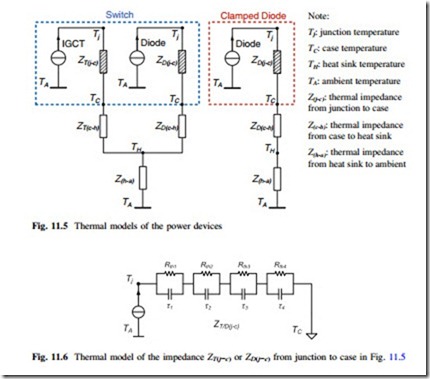
The thermal models of a single switch and clamped diode are indicated in Fig. 11.5, in which the thermal impedance from junction to case Z(j−c) is modeled as a four-layer Foster RC network, as shown in Fig. 11.6. Each of the thermal parameters can be found from the manufacturer datasheets and they are summarized in Table 11.2, where the thermal resistance Rth will decide the steady-state mean value of junction temperature, and the thermal capacitance (with time constant τ) will decide the dynamic change or fluctuation of the junction temperature. The ambient temperature is set to 50 °C and considered constant during the operation of converter, however, it may be changed depending on the operation site.
It is noted that the separately packaged IGCT and diodes are chosen because of the limitation for available products which can be found on the market. However, in a practical converter design, the IGCT/IGBT and its freewheeling diode are usually integrated and packaged together, the chip size for diode is about half of that for the IGCT/IGBT, accordingly, the thermal resistance of the diode from junction to heat sink is not consistent with its datasheet values but set to twice of the IGCT.
It is also noted that the thermal impedance between heat sink and ambient Z(h−a) in Fig. 11.5 is closely related to the design of the heat sink and to the layout for the
power devices, which are application-dependent and they are out of the scope of this special topic, therefore, the Z(h−a) is not included in the thermal analysis. However, it is worth to mention that the cost and structure of heat sink systems do have impacts on the thermal impedance and temperature profile of power devices. If heat sinks with small thermal resistance and large thermal capacitance are used, normally the temperature rise on the heat sink has smaller amplitude and longer time constant compared to the temperature rise inside the power devices. After the heat sink system is chosen and optimized, the temperature rise on the heat sink will be known and it is possible to be included in the analysis.
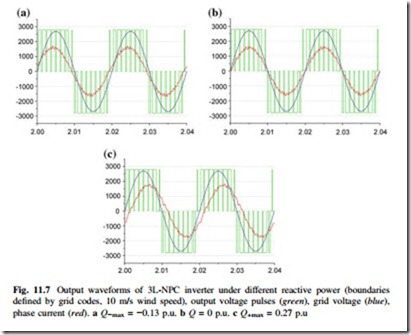
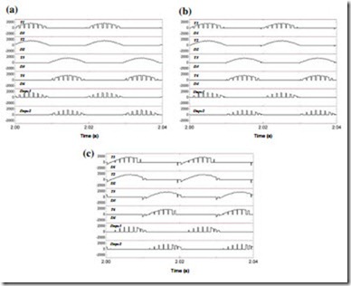
The simulation results regarding inverter outputs and current distribution are shown in Figs. 11.7 and 11.8 respectively, where the three extreme reactive power
conditions are introduced to the inverter when generating 0.63 p.u. active power at 10 m/s wind speed. It can be seen that when complying with the regulations by grid codes, the differences of converter outputs with the given three extreme reactive powers are insignificant.
The loss simulation results of the 3L-NPC wind power inverter are presented in Fig. 11.10, in which three given reactive power conditions are compared. It can be seen that there is no significant loss difference between the three conditions where different amounts of reactive power are introduced. The situation at the maximum overexcited reactive power boundary (Q+max = 0.27 p.u.) consumes slightly more loss in the outer switches and diode T1, D1 and inner switch T2 of the 3L-NPC inverter.
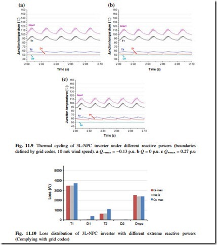
According to the junction temperature simulation results in Fig. 11.9, the thermal cycling in the most stressed devices of the clamping diode Dnpc as well as the outer switches T1 has no significant difference among the three reactive power operating points.
Effect of Reactive Power in Case of Paralleled Converters
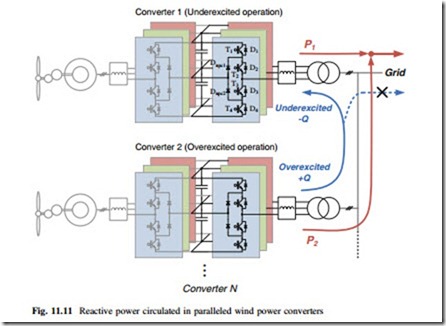
For wind power converter systems in a wind farm, the grid side inverters are connected as a local grid, therefore, the reactive power can basically be circulated among the inverters locally and not necessarily be seen in the power grid, as shown
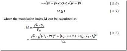
in Fig. 11.11. It can be seen that the underexcited reactive power –Q absorbed by converter 1 is generated/compensated by converter 2 which is under overexcited operation with +Q, and there is no (or less) reactive power injected into the power grid. On this condition the operation range of reactive power in converter 1 and converter 2 is not restrained by the grid codes but by the amplitude of load current as well as the converter output voltage, which is due to the limitations of device current rating and maximum modulation index of the power converter.
The new ranges of amplitude and phase angle of the load current with relation to the reactive power are shown in Fig. 11.12, which is restrained by
It can be seen that the operating range of reactive power is significantly extended compared to Fig. 11.4, and the ranges for overexcited and underexcited reactive current are unsymmetrical: The increase of Q+ will cause an increase of converter output voltage Uc, therefore the Q+ is first limited by the maximum modulation
index before it gets to the limitation of maximum device current rating. While the increase of Q− will cause a decrease of Uc and the modulation index, therefore Q− is only limited by the device current rating.
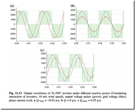
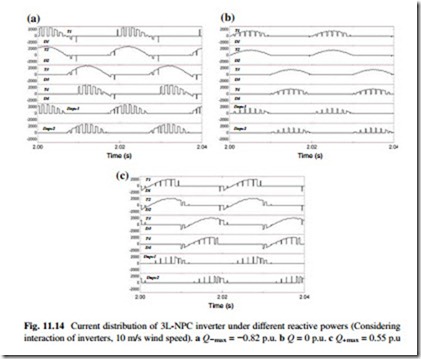
Another three extreme reactive power conditions when considering the inter- action between paralleled converters are investigated based on 10 m/s wind speed: the maximum underexcited reactive power boundary when Q−max (10 m/s) = −0.82 p. u., no reactive power when PF = 1, and maximum overexcited reactive current boundary when Q+max (10 m/s) = 0.5 p.u.
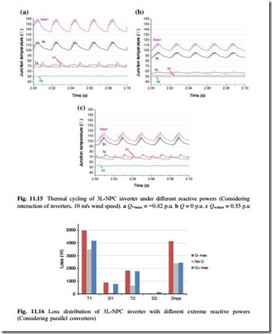
The simulation results regarding inverter outputs and current distribution are shown in Figs. 11.13 and 11.14 respectively, where the three extreme reactive power conditions are introduced when generating 0.63 p.u. active power at 10 m/s wind speed. It can be seen that when considering the interaction between paralleled converters, the converter output pulse width, amplitude, and phase angle of load current with the given three extreme reactive powers significantly differ from each other (Fig. 11.15).
The loss simulation results are presented in Fig. 11.16, in which three given reactive power conditions are compared when the interaction between parallel converters is considered. It can be seen that the situation at maximum overexcited
reactive power boundary (Q+max = 0.55 p.u.) consumes significantly more loss than the situation without reactive power in the outer switch T1, outer diode D1, inner switch T2 and clamping diode Dnpc of the 3L-NPC inverter. The major difference between overexcited and underexcited reactive power boundary is at the stress of the clamping diode, the latter has much less loss than the former one in Dnpc.
According to the junction temperature simulation results in Fig. 11.15, the thermal cycling of the most stressed device of the clamping diode Dnpc as well as outer switch T1 is significantly higher than the other two reactive power operating points.
In this special topic the operation conditions of converter with various reactive powers are analyzed based on p.u. system; with other converter ratings and designs the basic operation status, e.g., current loading and voltage outputs will be similar except for the switching frequency. Due to different parameters for loss and thermal models, the loss and junction temperature profile could deviate from the results obtained in this special topic if other power devices are applied. However, according to the device current loadings in Fig. 11.14, the extreme underexcited operation of converter will further increase the stress of Dnpc no matter which device is adopted, because the extreme underexcited operation leads to much higher current amplitude with more conduction time of Dnpc. The extreme overexcited operation of converter will further increase the stress of T1 for the same reasons.
