Principles of electrical engineering
Nomenclature and units
This book uses notation in accordance with the current British and International Standards. Units for engineering quantities are printed in upright roman characters, with a space between the numerical value and the unit, but no space between the decimal prefix and the unit, e.g. 275 kV. Compound units have a space, dot or solidus between the unit elements as appropriate, e.g. 1.5 N m, 9.81 m . s-2, or 300 m/s. Variable symbols are printed in italic typeface, e.g. V. For ac quantities, the instantaneous value is printed in lower case italic, peak value in lower case italic with caret (^), and rms value in upper case, e.g. i, î, I. Symbols for the important electrical quantities with their units are given in Table 2.1, and decimal prefix symbols are shown in Table 2.2. Graphical symbols for basic electrical engineering components are shown in Fig. 2.1.
Electromagnetic fields
Electric fields
Any object can take an electric or electrostatic charge. When the object is charged positively, it has a deficit of electrons, and when charged negatively it has an excess of electrons. The electron has the smallest known charge, –1.602 x10⁻¹⁹ C.
Charged objects produce an electric field. The electric field strength E (V/m) at a distance d (m) from an isolated point charge Q (C) in air or a vacuum is given by
where the permittivity of free space eo = 8.854 ´ 10-12 F/m. If the charge is inside an insulating material with relative permittivity er, the electric field strength becomes
Any charged object or particle experiences a force when inside an electric field. The force F (N) experienced by a charge Q (C) in an electric field strength E (V/m) is given by
Electric field strength is a vector quantity. The direction of the force on one charge due to the electric field of another is repulsive or attractive. Charges with the same polar- ity repel; charges with opposite polarities attract.
Work must be done to move charges of the same polarity together. The effort required is described by a voltage or electrostatic potential. The voltage at a point is defined as the work required to move a unit charge from infinity or from earth. (It is normally assumed that the earth is at zero potential.) Positively charged objects have a positive potential relative to the earth.
If a positively charged object is held some distance above the ground, then the volt- age at points between the earth and the object rises with distance from the ground, so that there is a potential gradient between the earth and the charged object. There is also an electric field pointing away from the object, towards the ground. The electric field strength is equal to the potential gradient, and opposite in direction.
Electric currents
Electric charges are static if they are separated by an insulator. If charges are separated by a conductor, they can move giving an electric current. A current of one ampere flows if one coulomb passes along the conductor every second.
A given current flowing through a thin wire represents a greater density of current than if it flowed through a thicker wire. The current density J (A/m2) in a wire with cross section area A (m2) carrying a current I (A) is given by
For wires made from most conducting materials, the current flowing through the wire is directly related to the difference in potential between the ends of the wire.
Ohm’s law gives this relationship between the potential difference V (V) and the current I (A) as
where R (W) is the resistance, and G (S) = 1/R is the conductance (Fig. 2.2). For a wire of length l and cross section area A, these quantities depend on the resistivity r (W . m) and conductivity s (S/m) of the material
For materials normally described as conductors r is small, while for insulators r is large. Semiconductors have resistivity in between these extremes, and their properties are usually very dependent on purity and temperature.
In metal conductors, the resistivity increases with temperature approximately linearly:
for a conductor with resistance R at reference temperature To. This is explained in more detail in section 3.4.1.
Charges can be stored on conducting objects if the charge is prevented from moving by an insulator. The potential of the charged conductor depends on the capacitance C (F) of the metal/insulator object, which is a function of its geometry. The charge is related to the potential by
A simple parallel-plate capacitor, with plate area A, insulator thickness d and relative permittivity er has capacitance
Magnetic fields
A flow of current through a wire produces a magnetic field in a circular path around the wire. For a current flowing forwards, the magnetic field follows a clockwise path, as given by the right-hand corkscrew rule (Fig. 2.3). The magnetic field strength
For a more complicated geometry, Ampère’s law relates the number of turns N in a coil, each carrying a current I, to the magnetic field strength H and the distance around the lines of magnetic field l.
where Fm (ampere-turns) is the magnetomotive force (mmf). This only works for situations where H is uniform along the lines of magnetic field.
The magnetic field produced by a current does not depend on the material surrounding the wire. However, the magnetic force on other conductors is greatly affected by the presence of ferromagnetic materials, such as iron or steel. The magnetic field produces a magnetic flux density B (T) in air or vacuum
where the permeability of free space mo = 4p ´ 10–7 H/m. In a ferromagnetic material with relative permeability mr
A second conductor of length l carrying an electric current I will experience a force F in a magnetic flux density B
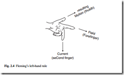
The force is at right angles to both the wire and the magnetic field. Its direction is given by Fleming’s left-hand rule (Fig. 2.4). If the magnetic field is not itself perpendicular to the wire, then the force is reduced; only the component of B at right angles to the wire should be used.
The mmf Fm required to cause a magnetic flux F to flow through a region of length l and cross section area A is given by the reluctance Rm (A/Wb) or the permeance L (Wb/A) of the region
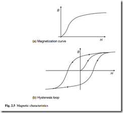
In ideal materials, the flux density B is directly proportional to the magnetic field strength H. In ferromagnetic materials the relation between B and H is non-linear (Fig. 2.5(a)), and also depends on the previous magnetic history of the sample. The magnetization or hysteresis or BH loop of the material is followed as the applied mag- netic field is changed (Fig. 2.5(b)). Energy is dissipated as heat in the material as the operating point is forced around the loop, giving hysteresis loss in the material. These concepts are developed further in section 3.2.
Electromagnetism
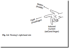
Any change in the magnetic field near a wire generates a voltage in the wire by electromagnetic induction. The changing field can be caused by moving the wire in the magnetic field. For a length l of wire moving sideways at speed n (m/s) across a magnetic flux density B, the induced voltage or electromotive force (emf) is given by
The direction of the induced voltage is given by Fleming’s right-hand rule (Fig. 2.6). An emf can also be produced by keeping the wire stationary and changing the
The direction of the induced emf is given by Lenz’s law, which says that the induced voltage is in the direction such that, if the voltage caused a current to flow in the wire, the magnetic field produced by this current would oppose the change in y. The negative sign indicates the opposing nature of the emf.
A current flowing in a simple coil produces a magnetic field. Any change in the cur- rent will change the magnetic field, which will in turn induce a back-emf in the coil. The self-inductance or just inductance L (H) of the coil relates the induced voltage to the rate of change of current
Two coils placed close together will interact. The magnetic field of one coil will link with the wire of the second. Changing the current in the primary coil will induce a volt- age in the secondary coil, given by the mutual inductance M (H)
Placing the coils very close together, on the same former, gives close coupling of the coils. The magnetic flux linking the primary coil nearly all links the secondary coil. The voltages induced in the primary and secondary coils are each proportional to their number of turns, so that
A two-winding transformer consists of two coils wound on the same ferromagnetic core. An autotransformer has only one coil with tapping points. The voltage across each section is proportional to the number of turns in the section. Transformer action is described in detail in section 6.1.


