Power Transformers
Introduction
The transformer forms the basis of all ac power-distribution systems. In the most basic definition, a trans- former is a device that magnetically links two or more circuits for time-varying voltage and current. Magnetic coupling has a number of intrinsic advantages, including:
• DC isolation between the circuits
• The ability to match the voltage and current capability of a source to a load
• The ability to change the magnitude of the voltage and current from one side of the transformer to the other
• The ability to change the phases of voltage and current from one side of the device to the other
Inductive Properties
Inductance is, primarily, a geometrical property of a current-carrying element in an electrical circuit [1]. A circuit element with this property may be termed an inductor. The magnitude and, for that matter, the fre- quency dependence of inductance also depend on the material environment of that element. Similar remarks to these could — of course — be used to define capacitance; inductance and capacitance are invari- ably intimately related in electronic circuits. One reason is that both are (electrical) energy storage devices in time-varying electronic systems. Capacitance is, however, a measure of the capability of a (potential) circuit element to store charge and, thereby, electric field energy; inductance, by contrast, is a measure of a circuit element’s ability to store magnetic field energy. Because a magnetic field is derived from current flow, inductance is always associated with current-carrying circuit elements. This dichotomy extends also to the matter of frequency dependence. At zero signal frequency, for example, an (ideal) capacitor has infinite impedance, whereas the inductor has zero impedance; at infinite frequency, the opposite is true.
The concept of inductance or, more correctly, self-inductance is, perhaps, best illustrated by the example of a current-carrying conducting coil of N circular turns (see Figure 4.1). When a current I flows through this circuit, as described, a magnetic field is generated inside and around the coil turns, in accordance with
Ampere’s law. Flux linkage Λ is defined by how much of the total magnetic flux φ threads all of the turns of
the coil, multiplied by the total numbers of turns N. Thus, in simple algebraic terms:
1This section was adapted from Parker, M. R., and W. E. Webb, “Magnetic Materials for Inductive Pro- cesses,” in The Electronics Handbook, 2nd ed., J. C. Whitaker (Ed.), CRC Press, Boca Raton, FL, 2005. Used with permission.
The SI unit of inductance is the henry (H) if I is in amperes, Λ in webers, A in square meters, and B in teslas (webers/square meter). The inductance of some current-carrying elements of comparatively simple geometry is described in approximate form next.
Note that, in the limit of a becoming vanishingly small, the short solenoid takes on the appearance of a long solenoid and Equation 4.6 reduces to Equation 4.4.
In the limit of l approaching zero in Equation 4.6, we have a flat coil of N turns, radius a, whose inductance is approximately
The Toroid
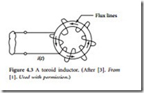
Another simple classic geometry (Figure 4.3) is the tor- oid [1]. This doughnut-shaped winding is a close rela- tive of the long solenoid. Indeed, it may be viewed as a long solenoid whose ends have been joined. Accordingly, the B-field inside the toroid may be given, approximately, by Equation 4.4, with the modification that the length l is replaced by 2r, where r is the (mean) radius of
the toroid. A crude approximation for the inductance of the toroid, when r is much greater than the radius of the individual windings, is, therefore,
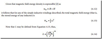
All of the preceding described current elements were characterized by air-filled windings [1]. In fact, the formulas of the preceding equations are essentially valid if the windings encompass any condensed mat- ter other than a magnetic (i.e., ferromagnetic/ferrimagnetic, etc.) material. If, however, any of the described windings are constructed around a magnetic material of permeability μ, then in each of the formulas of Equation 4.4 through Equation 4.10, μ0 is replaced by μ. Now, for magnetic materials μ is, typically, much greater than μ0. The actual value of μ depends crucially on: (1) the current signal frequency, and (2) the chemical identity and temperature of the magnetic material comprising the inductive element as well as on the details of its microstructure.
In inductive devices, one will typically find soft magnetic materials employed as the core medium. Here, a soft magnetic material is one in which the relative permeability μr , defined as


