Predictive Maintenance and PQ Measurements
Introduction
In this section a discussion is provided on PQ measurements that can be used as predictive maintenance of power system and plant equipment. Unexpected failures can be avoided in both production equipment and power system apparatus when basic PQ measurements are added to maintenance procedures. Insurance claims data in the NFPA 70B indicates that roughly half of the cost associated with electrical failures could be prevented by regular maintenance. A study published in IEEE 493-1997 says that a poorly maintained system can attribute 49% of its failures to lack of maintenance. To determine the cost of a failure, it helps to consider the cost of lost income (gross margin) due to downtime, cost of labor to troubleshoot, patch, clean up, repair and restart, and cost of damaged equipment and materials, including repairs, replacements and scrapped materials.
Predictive maintenance of PQ focuses on a small set of measurements that can predict power distribution or critical load failures. By checking the PQ at critical loads, one can see the effect of the electrical system up to the load. The predictive maintenance inspection program should include motors, genera- tors, pumps, A/C units, fans, gearboxes, or chillers on site. The voltage stability, HD, and unbalance voltages are good indicators of load and distribution system health and can be taken and recorded quickly with little incremental labor. Current measurements can identify changes in the way the load parameters are changing. All of these measurements can be taken without halting opera- tions and measurement data can easily be entered into computer maintenance management software (CMMS) and plotted over time (see Section 1.4.3.5 for information on CMMS). For each measurement point or piece of equipment, limits can be set to trigger corrective action. Limits should be set well below the point of failure, and as time goes on limits may be tightened or loosened by analyzing historical data. The appropriate limits depend somewhat on the ability of the loads to deal with power variation. But for most equipment, the maintenance team can devise a set of default, house limits based on industry standards and experience. The cost of three-phase power analyzers and other PQ tools is lower now than before and measurements discussed in this section should be part of the predictive maintenance program.
Safety Standards for Test Instruments
12.6.2.1 Test Instrument Standards
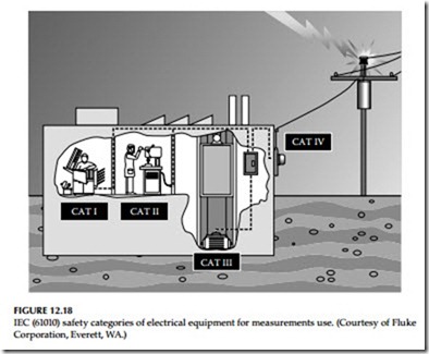
IEC 61010 establishes international safety requirements for low voltage (1000 V or less) electrical equipment for measurement, control, and laboratory use. The low voltage power distribution system is divided into four categories, based on the proximity to the power source. Within each category are voltage listings—1000, 600, 300 V, etc. The key concept to understand is that you should use a meter rated to the highest category, as well as the highest volt- age, that you might be working in. For PQ troubleshooting, a meter rated to CAT IV-600 V should always be used. The CAT ratings should be marked near the voltage inputs of the instrument. IEC 61010 requires increased pro- tection against the hazards of transient overvoltages. Transients can cause an arc-over inside an inadequately protected meter. When that arc-over occurs in a high energy environment, such as a three-phase feeder circuit, the result can be a dangerous arc blast. The potential exists for serious harm to person- nel as well as damage to the meter. Also, when undertaking PQ measurements,
the personnel should follow the requirements of safety-related work practices listed in Chapter 13 of the NFPA 70E, and rules promulgated by OSHA (Code of Federal Regulations, Title 29, Subtitle B, Chapter XVII, subpart S, paragraph 1910.331–1910.335) for safety-related work practices. Further, the instrument’s manufacturer application notes and information should be con- sulted when making such measurements. The four categories of electrical equipment for measurements are depicted in Figure 12.18.
Manufacturers can self-certify that they meet IEC 61010 specifications, but there are obvious pitfalls for the end-user in self-certification. Certification by an independent testing laboratory provides assurance that the meter meets IEC requirements. Before using the test instruments, look for a symbol and listing number of an independent testing laboratory such as UL, CSA, TÜV, VDE, or others.
12.6.2.2 Instruments for PQ Measurements
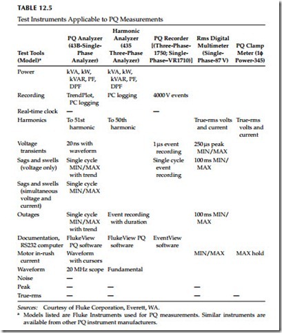
PQ monitoring requires a variety of instruments due to the many different measurements that must be performed. A general description of test instruments is given in this to make the reader familiar with the instruments that are normally used for PQ surveys and/or measurements. As an example, Table 12.5 lists the test instruments manufactured by Fluke Corporation which are applicable to the type of measurements discussed in this section. Similar instruments are available from other manufactures. Note that a true-rms multimeter, ammeter,
ground impedance tester, and power line monitor/analyzer are absolutely essential equipment for minimum effective power disturbance detection and analysis.
True-rms multimeters: A true-rms digital multimeter is used to measure voltage and continuity.
True-rms clamp-on ammeters: A true-rms clamp-on ammeter is used to mea- sure current and analyze current waveforms, particularly when sinusoidal waveforms are involved. It is recommended due to the ease of use and broad bandwidth characteristics of transformer-based meter designs. Several types of ammeters currently are available such as direct reading and indirect read- ing ammeters.
Ground impedance testers: Aground impedance tester is a multifunctional instrument designed to detect wiring and ground problems in low-voltage power distribution systems. Such problems can include: wiring errors, neutral–ground (N–G) shorts and reversals, IG shorts ground, and neutral impedance shorts. Some testers are designed for use on 120V AC single-phase systems while others can be used on both single and three-phase systems up to 600V AC.
Earth ground tester: An earth ground tester is used to measure the ground electrode impedance. Ground resistance tests should be conducted with a fall-of-potential method instrument. Clamp-on instruments that do not require the grounding electrode to be isolated from the building may be used with the understanding that these instrument may not give the most accurate readings of the ground electrode impedance.
Oscilloscope: An oscilloscope can be used to detect harmonics in an electrical system. It also can be used for noise measurements when combined with a line decoupler. In this case, the input is connected to the voltage of interest with the appropriate lead. If a voltage above the range of the oscilloscope is to be examined, probes with resistance-divider networks are available to extend the range of the instrument.
Spectrum analyzers: A spectrum analyzer equipped with appropriate measurement capabilities can be used to measure harmonics, electrical noise, and frequency deviations. Special-purpose harmonic meters or low frequency or broadband spectrum analyzers also can be used to measure these voltage and current disturbances.
Static meters: Static meters typically are used to measure ESD. These are handheld devices.
Psychrometer: A psychrometer is used to measure temperature and humid- ity in the environment, although such measurements also can be made with power monitoring devices equipped with special probes.
Field strength meter: A field strength meter equipped with a special probe can be used to measure electric or magnetic field strength.
Infrared detectors: Infrared detectors can be used to detect overheating of transformers, circuit breakers, and other electrical apparatus.


