Power Factor
Introduction
Power factor (PF) is an important, but often misunderstood, element of ac power system design and opera- tion. It is defined as the ratio of true power to apparent power, generally expressed as a percentage. (PF also may be expressed as a decimal value.) Reactive loads (inductive or capacitive) act on power systems to shift the current out of phase with the voltage. The cosine of the resulting angle between the current and voltage is the power factor.
Fundamental Principles
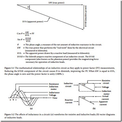
A utility line that is feeding an inductive load (which is most often the case) is said to have a lagging power factor, whereas a line feeding a capacitive load has a leading power factor. (See Figure 3.1.) A poor power factor will result in excessive losses along utility company feeder lines because more current is required to sup- ply a given load with a low power factor than the same load with a power factor close to unity.
For example, a motor requiring 5 kW from the line is connected to the utility service entrance. If it has a power factor of 86%, the apparent power demanded by the load will be 5 kW divided by 86%, or more than 5.8 kW. The true power is 5 kW, and the apparent power is 5.8 kW. The same amount of work is being done by the motor, but the closer the power factor is to unity, the more efficient the system. To expand upon this example, for a single-phase electric motor, the actual power is the sum of several components, namely:
• The work performed by the system, specifically lifting, moving, or otherwise controlling an object
• Heat developed by the power that is lost in the motor winding resistance
• Heat developed in the motor iron through eddy-current and hysteresis losses
• Frictional losses in the motor bearings
• Air friction losses in turning the motor rotor
All these values are expressed in watts or kilowatts, and can be measured with a wattmeter. They represent the actual power. The apparent power is determined by measuring the current and voltage with an ammeter and a voltmeter, then calculating the product of the two. In the single-phase motor example, the apparent power thus obtained is greater than the actual power. The reason for this is the power factor.
The PF reflects the differences that exist between different types of loads. A soldering iron is a purely resistive load that converts current directly into heat. The current is called actual current because it contributes directly to the production of actual power. On the other hand, single-phase electric motor represents a partially inductive load. The motor current consists of actual current that is converted into actual power and a magnetizing current that is used to generate the magnetic field required for operation of the device. This magnetizing current corresponds to an exchange of energy between the power source and the motor, but it is not converted into actual power. This current is identified as the reactive current in the circuit.
As illustrated in Figure 3.2, in a resistive circuit, the current is in phase with the voltage. In a purely inductive circuit, the current lags the voltage by 90˚. This relationship can be represented graphically by vec- tors, as shown in the figure. For a circuit with both inductive and resistive components, as in the motor example, the two conditions exist simultaneously. The distribution between the actual power and the reactive power is illustrated in Figure 3.3. The power factor, which has been defined previously as the ratio between actual power and apparent power, is also the cosine of the angle θ. The greater the angle θ becomes, the lower the power factor.
Determining the power factor for a given element of a power-distribution system is complicated by the variety of loads typically connected. Different loads present different PF components:
• Lighting. The PF for most incandescent lamps is unity. Fluorescent lamps usually have a low power factor; 50% is typical. Fluorescent lamps sometimes are supplied with compensation devices to correct for low power factor. Mercury vapor lamps have a low PF; 40 to 60% is typical. Again, such devices can be supplied with compensation devices.
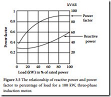
• Electric motors. The PF of an induction motor varies with the load, as shown in Figure 3.4. Unloaded or lightly loaded motors exhibit a low PF. Figure 3.5 illustrates the variation of PF and reactive power for varying loads on a three-phase induction motor. Synchronous motors provide
good PF when their excitation is adjusted properly. Synchronous motors also can be overexcited to exhibit a leading power factor and, therefore, can be used to improve the power factor of a facility.
• Heating systems. Most heating systems used in ovens or dryers present a PF of close to unity.
• Welding equipment. Electric arc welders usually have a low PF; 60% is typical.
• Distribution transformers. The PF of a transformer varies considerably as a function of the load applied to the device, as well as the design of the transformer. An unloaded transformer would be highly inductive and, therefore, would exhibit a low PF.
Power factor, in the classical power triad representation presented here, is more appropriately referred to as displacement power factor (DPF). DPF is that portion of the power factor that is attributable to phase displacement between the source voltage and the load current at the fundamental frequency [1]. The vector diagram power triangle models real and reactive power at the fundamental frequency of the electrical power sys- tem. Displacement power factor does not consider that portion of the power factor attributable to harmonic load current.
The total power factor (TPF) can be derived by revisiting the definition of power factor as a measurement of efficiency. TPF, then, is the ratio of real power to total power consumed in the system:
TPF = Total power factor KW = Real power consumed by the electrical system kVAtotal = Total power (composed of real, reactive, and harmonic power)
The TPF in a system can be low because of high reactive power consumption or high harmonic power consumption, resulting in high apparent power in the denominator. DPF is always greater than TPF when harmonic load currents exist.


