High-Potential Test
AC or DC voltage high potential test may be performed on machines stator windings. The size of the machine windings (i.e., insulation volume) will deter- mine whether an AC high potential test can be performed in the field because if the machine is very large the field portable AC high potential test set may not have the capability to charge the winding insulation. The DC voltage high- potential test is discussed in Section 2.7 in Chapter 2, therefore this discussion only addresses the AC voltage high potential test for machines.
The high-potential test of the armature (stator) winding of a large motor or generator is preceded by a visual inspection and insulation resistance measure- ments. It provides the moment of truth concerning the condition of insulation. High-potential tests may be performed with the rotor in place or with it removed. It is advantageous to consult and follow the manufacturer’s recommendations and schedules, taking into account the operating history of a machine. For example, it is recommended that on large machines the rotor be removed every 5 years and high-potential tests performed every 2–3 years.
To prepare the tests, the machine terminals are disconnected from the bus bars, the neutral connection is broken so that each phase winding may be subjected to a test voltage with respect to the other phase windings, and the rotor (if in place) is grounded. Protective ground cables should be connected to all disconnected bus bars and the neutral conductor. Each phase winding is short circuited so that uniform test voltage will be applied to each end. A test lead is attached to each phase winding and secured and terminated so that a convenient connection to the high-voltage test lead and to ground can be made. Temporary insulation, plastic bags over sharp points, and tie offs must be arranged to give correct clearance for the test voltage. A minimum of clearance of 7 in. per 10 kV, 60 Hz, is recommended for base conductor clearance.
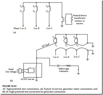
The 60 Hz AC high-potential test applies stresses to machine winding as near as possible to those that normally exist under operating conditions. Even though the 60 Hz test is preferred over DC or 0.1 Hz tests, there are few AC sets of adequate size (kVA) available to perform this test on large machines. The size of the test set may be calculated from the following formula: kVA = 0.377 CE2, where C is the machine winding capacitance in microfarads and E is the maximum test voltage in kilovolts. For example, inservice operation on a 13.8 kV machine, each phase winding is stressed at 13.8/ —or approximately to ground with midpoint only at 4 kV to ground. The ends of windings T4, T5, and T6 (Figure 10.42a) are nearly at zero stress. The insulation toward the ends T4, T5, and T6, could be worn and still not fail in service unless damage to the winding becomes severe. During the high-voltage test, the windings are short circuited. The high-voltage lead is connected to both T1 and T4 and later
to T2 and T3 and T5 and T6. Both ends of the winding are subjected to the same potential, full-test voltage. Weak points of any part of the winding that might not fail in service should fail under test. This is desirable since worn-out coils should be repaired or replaced to avoid unexpected and sudden failure.
Protection against accidental application of an overvoltage can be provided by connecting an air gap voltmeter with an appropriate series resistor between the high-voltage test lead and ground. A setting of 2–5 kV above the high-voltage test value will provide necessary protection. The test connection is shown in Figure 10.42b.
High-potential tests are used in connection with manufacture, repair or reconditioning, and routine testing of machines. The following test procedures and safety precautions are important while conducting these tests:
• Keep everyone from coming in contact with any part of the circuit or apparatus while the test is being conducted.
• After the test has been made, never touch the winding tested until it has been correctly connected to ground to remove any static charge it may have retained.
• All leads to the circuit being tested should be connected to one terminal of the source of the test voltage. All leads to all other circuits and all metal parts should be connected to ground. No leads are to be left unconnected for high-potential tests as this may cause an extremely severe strain at some point of the winding.
• When making an AC voltage high-potential test, the voltage should be increased to full voltage as rapidly as consistent with its value. This voltage should be maintained for 1 min. After completion of the test, the voltage should be reduced at a rate that will bring it to one- quarter value or less in not more than 15 s.
• When making DC voltage high-potential test, the voltage should be applied in controlled voltage steps. Refer to Chapter 2 for details on performing DC voltage high-potential tests.
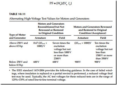
• Effective AC voltages to apply to motors and generators are listed in Table 10.11.
10.11.3 PF Test
This method allows successful ground insulation tests on machine individ- ual stator phase windings. This test is usually connected up to and including 100% line-to-ground voltage. The PF is the ratio of the stator insulation loss (watts) and volt-amperes at a specified test voltage. This can be represented by the following equation:
The evaluation of the test data is best interpreted by comparing with previous test results or by comparing test results among phases or with those test results obtained on units of similar manufacture and rating. It is gener- ally found that machines up to 24 kV will have a PF of 3% or less, depending upon the insulation system. The PF tip-up test may also be performed to further evaluate the insulation system. The tip-up test is defined as the increase in PF as voltage is increased from 2 kV to operating voltage. Refer to Section 3.6.7 in Chapter 3 for more details on PF testing.
Dissipation Factor Tan d Test
The machine winding may be considered as consisting of capacitance and resistance.
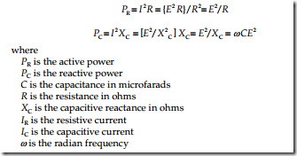
The active (resistive) power and reactive (capacitive) power can be repre- sented by the following equations:
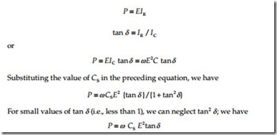
The active power of the resistance in this equivalent circuit represents all capacitor losses. These losses occur on the surface and in the interior of the dielectric. The power P determines the loss of the capacitor. The dissipation factor tan d measuring bridge (Schering bridge) is designed to simulate the capacitor (the machine winding) by a series connection of resistance Rs and capacitance Cs. The corresponding values for the series connection for a given frequency can be converted by the following formula:
The value of CS is measured as Cx by the Schering bridge. The resistance and the inductance of the leads have to be considered for high capacitances and resistances; otherwise they are negligible. The PF and tan d tests are discussed in more detail in Chapter 3.


