Centrifugal governors
Spark-ignition engines have a built-in governor in the form of a throttle valve that, even wide open, limits the amount of air passing into the engine. Diesels have no such limitation, since surplus air is always available for combustion. Engine speed
depends solely upon the amount of fuel delivered. If the same volume of fuel necessary to cope with severe loads were delivered under no-load conditions, the engine would rev itself to destruction. Consequently, all diesel engines need some sort of speed-limiting governor.
Most governors also control idle speed, a task that verges on the impossible for human operators. This is because the miniscule amount of fuel injected during idle exaggerates the effects of rack movement. Automotive applications are particularly critical in this regard. Idle speed must be adjusted for sudden loads, as when the air- conditioner compressor cycles on and off, and when the driver turns the wheel and engages the power-steering pump.
In addition to limiting no-load speed and regulating idle speed, many governors function over the whole rpm band. The operator sets the throttle to the desired speed and the governor adjusts fuel delivery to maintain that speed under load. The degree of speed stability varies with the application. No governor acts instantaneously—the engine slows under load before the governor can react. Course regulation holds speed changes to about 5% over and under the desired rpm, and is adequate for most applications. Fine regulation, of the kind demanded by AC generators, cuts the speed variation by half or less.
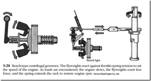
Centrifugal governors sense engine speed with flyweights and throttle position with spring tension. Figure 5-28 illustrates the principle: As engine speed increases, the spinning flyweights open to reduce fuel delivery. As the throttle is opened, the spring applies a restraining force on the flyweight mechanism to raise engine speed.
So much for theory. In practice, centrifugal governors demonstrate a level of mechanical complexity that seems almost bizarre, in this era of digital electronics.
But millions of these governors are in use and some discussion of repair seems appropriate.
Service
Governor malfunctions—hunting, sticking, refusal to hold adjustments—can usually be traced to binding pivots. In some cases, removing the cover and giving the internal parts a thorough cleaning is all that’s necessary. If more work is needed, the governor and pump should be put into the hands of a specialist.
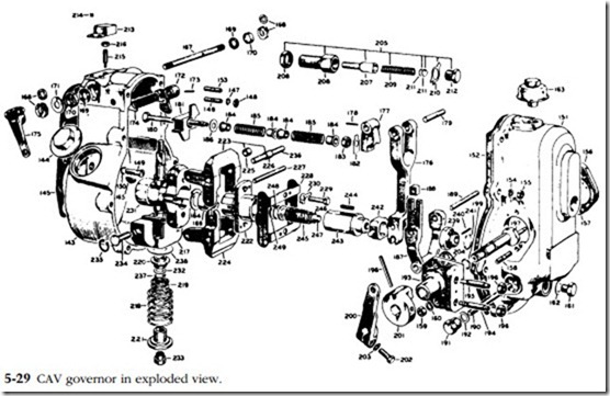
To appreciate why this is so, consider the matter of bushing replacement, which seems like a simple enough job. Using the CAV unit as a model, the critical bushings
are those at the flywheel pivots (225 in Fig. 5-29) and the sliding bushing (231) on the governor sleeve. To remove and install the flyweights you will need CAV special tool 7044-8. Bushing press in, but factory reamers are needed to size them properly. And a governor with enough hours on it to wear out bushings will almost surely need recalibration, which can only be accomplished with a factory tooling that cor- relates piston stroke with rack position.


