Different Concepts for the Energy Conversion System in Offshore Wind Energy
Each concept of HVDC transmission and offshore grid is directly related to the type of energy conversion system in the side of the generators. Double fed induction generators are the most common alternative for mainland wind farms.
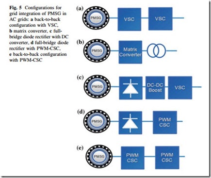
b matrix converter, c full- bridge diode rectifier with DC converter, d full-bridge diode rectifier with PWM-CSC e back-to-back configuration with PWM-CSC
However, for offshore wind energy is the PMSG the most suitable option, espe- cially on DC grids offshore. PMSGs require a full converter to be integrated to the main grid. Different type of converters can be used according to the type of offshore grid.
In the case of AC grids as the one shown in Fig. 3, the PMSG must to be integrated using AC/AC converters. Different configurations have been proposed as shown in Fig. 5. They come from voltage source-based converters to current source-based converters. Back-to-back configuration with voltage source con- verters (VSCs) is the most common type of technology (see Fig. 5a). It permits to control the active and reactive power in both sides of the converter. Therefore, it can be used with both PMSG and induction machines. A second alternative is the matrix converter (see Fig. 5b). It is an AC/AC converter without intermediate stage of DC conversion. It can control voltage in the input and current on the output. Consequently, the machine and power factor can be directly controlled. Among its advantages is the reduced size high reliability. PMSG can be integrated though a full-bridge diode rectifier as shown in Fig. 5c and d. In both cases, the output voltage varies according to the wind velocity and hence VSC cannot be used directly on the output. Consequently, the converter must be integrated though an intermediate stage of DC/DC conversion. Another alternative is to use pulse
width modulated current source converter (PWM-CSC). Last option is promising due to the high efficiency of the diode rectifier and the high reliability of the PWM-CSC. Finally, a back-to-back configuration with PWM-CSC is also an option as shown in Fig. 5e.
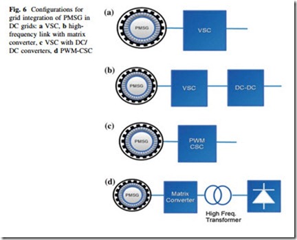
In the case of parallel DC grid, the topology of the converter depends on the type of connection, i.e., series or parallel. For parallel connection, the converters based on VSCs are the most suitable. A classic VSC as shown in Fig. 6a is enough for controlling the machine. However, it could be required a DC/DC converter in order to step-up the output voltage as shown in Fig. 6b.
In series connection, the most suitable technology is the current source convert as shown in Fig. 6c. This converter can control the machine based on the current shared by the all the converters connected in series. The output voltage varies according to the wind velocity. Finally, a configuration based on reduced matrix converter (RMC) and high-frequency transformer is shown in Fig. 6d. This topology operates in a very similar way as the PWM-CSC. However, the high- frequency transformer increases the voltage and permits galvanic isolation.


