Distribution Substations
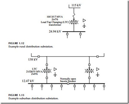
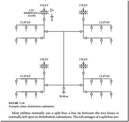
Distribution substations come in many sizes and configurations. A small rural substation may have a nominal rating of 5 MVA while an urban station may be over 200 MVA. Figure 1.12 through Figure 1.14 show examples of small, medium, and large substations. As much as possible, many utilities have standardized substation layouts, transformer sizes, relaying systems, and automation and SCADA (supervisory control and data acquisition) facilities. Most distribution substation bus configurations are simple with limited redundancy. Transformers smaller than 10 MVA are normally protected with fuses, but fuses are also used for transformers to 20 or 30 MVA. Fuses are inexpensive and simple; they don’t need control power and take up little space. Fuses are not particularly sensitive, especially for evolving internal faults. Larger transformers normally have relay protection that operates a circuit switcher
or a circuit breaker. Relays often include differential protection, sudden- pressure relays, and overcurrent relays. Both the differential protection and the sudden-pressure relays are sensitive enough to detect internal failures and clear the circuit to limit additional damage to the transformer. Occasion- ally, relays operate a high-side grounding switch instead of an interrupter. When the grounding switch engages, it creates a bolted fault that is cleared by an upstream device or devices.
The feeder interrupting devices are normally relayed circuit breakers, either free-standing units or metal-enclosed switchgear. Many utilities also use reclosers instead of breakers, especially at smaller substations.
Station transformers are normally protected by differential relays which trip if the current into the transformer is not very close to the current out of the transformer. Relaying may also include pressure sensors. The high- side protective device is often a circuit switcher but may also be fuses or a circuit breaker.
Two-bank stations are very common (Figure 1.13); these are the standard design for many utilities. Normally, utilities size the transformers so that if either transformer fails, the remaining unit can carry the entire substation’s load. Utility practices vary on how much safety margin is built into this calculation, and load growth can eat into the redundancy.
Most utilities normally use a split bus: a bus tie between the two buses is normally left open in distribution substations. The advantages of a split bus are:
• Lower fault current — This is the main reason that bus ties are open.
For a two-bank station with equal transformers, opening the bus tie
cuts fault current in half.
• Circulating current — With a split bus, current cannot circulate through both transformers.
• Bus regulation — Bus voltage regulation is also simpler with a split bus. With the tie closed, control of paralleled tap changers is more difficult.
Having the bus tie closed has some advantages, and many utilities use closed ties under some circumstances. A closed bus tie is better for
• Secondary networks — When feeders from each bus supply either spot or grid secondary networks, closed bus ties help prevent circulating current through the secondary networks.
• Unequal loading — A closed bus tie helps balance the loading on the transformers. If the set of feeders on one bus has significantly different loading patterns (either seasonal or daily), then a closed bus tie helps even out the loading (and aging) of the two transformers.
Whether the bus tie is open or closed has little impact on reliability. In the uncommon event that one transformer fails, both designs allow the station to be reconfigured so that one transformer supplies both bus feeders. The closed-tie scenario is somewhat better in that an automated system can reconfigure the ties without total loss of voltage to customers (customers do see a very large voltage sag). In general, both designs perform about the same for voltage sags.
Urban substations are more likely to have more complicated bus arrangements. These could include ring buses or breaker-and-a-half schemes. Figure 1.14 shows an example of a large urban substation with feeders supplying secondary networks. If feeders are supplying secondary networks, it is not critical to maintain continuity to each feeder, but it is important to prevent loss of any one bus section or piece of equipment from shutting down the network (an N-1 design).
For more information on distribution substations, see (RUS 1724E-300, 2001; Westinghouse Electric Corporation, 1965).

