Rigging
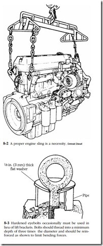
Figure 8-2 illustrates the proper lifting tackle for a large engine. Note how the spreader bar and adjustable crossheads keep the chains vertical to hook loads.
The engine shown incorporates lift brackets; less serious engines do not, and the mechanic is left to his own devising. In general, attachment points should straddle the center of gravity of the engine in two planes, so that it lifts horizontally without tilting. Chains must clear vulnerable parts, such as rocker covers and fuel lines. Lift brackets made of 3/ in. flame-cut steel plate are the ideal, but forged eyebolts (available from fastener supply houses) are often more practical. A spreader bar will eliminate most bending loads, but there are times when chain angles of less than 90° cannot be entirely avoided. Reduce the bending load seen by the eyebolt with a short length of pipe and heavy washer, as shown in Fig. 8-3.
In no case should chains be bolted directly to the block without the intermediary of a bracket or eyebolt. Nor is multistrand steel cable appropriate for this kind of knock-about service.
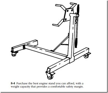
Figure 8-4 illustrates a minimal engine stand, suitable for engines in the 600-lb. class. Better stands usually attach at the side of the block (as opposed to the flywheel flange) and can be raised and lowered.
Note: A mechanic can get into trouble with one of these revolving-head stands. Inverting an assembled engine with the turbocharger intact can dump oil from the turbocharger sump into one or more cylinders. Subsequent attempts to start the flooded engine might result in bent connecting rods or worse.

