Caterpillar EMS
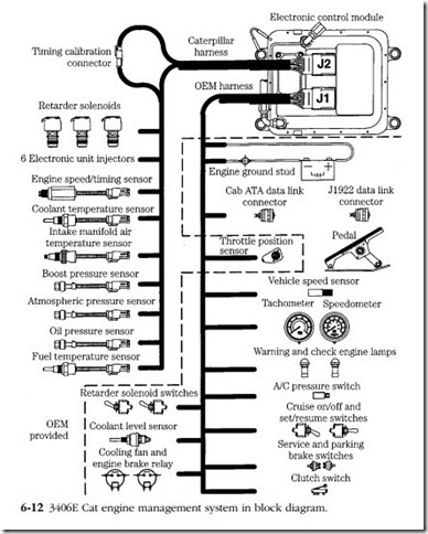
Figure 6-12 illustrates the EMS used on Caterpillar 3116, 3176, 3406E, and 3500 engines. It is a relatively simple system, without the bells and whistles mandated by current emissions regulations. The ECM mounts on the engine, which reduces the electromagnetic radiation given off by the harness, simplifies packaging, and enables the computer to be cooled by fuel. A major engineering effort was required to isolate the electronics from the heat, vibration, solvents, steam, and water blasts that engines are exposed to.
All sensors, with the exception of the oil pressure sensor, input data for efficient fuel allocation. Abnormally low or high sensor readings cause the ECM to set one or
more trouble codes, which can be retrieved by connecting a scan tool to the SAE J1922 data link connector. The only computer-controlled actuators in this particular system are the electronic unit injectors (EUIs), cooling fan, and cruise control.
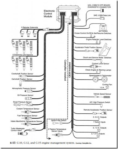
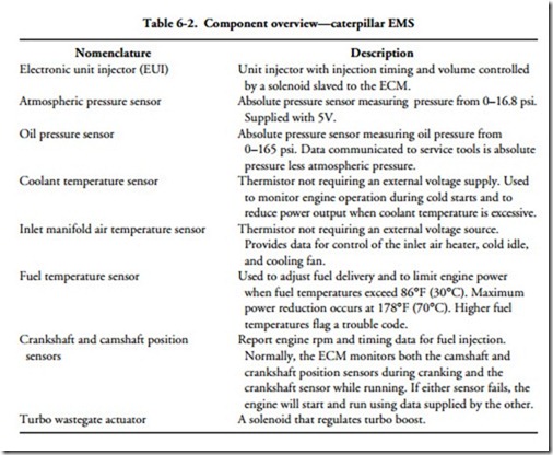
A more sophisticated system used on current C-10, C-12, and C-15 truck engines is illustrated in Fig. 6-13. Sensor and actuator functions for this and the earlier Cat system
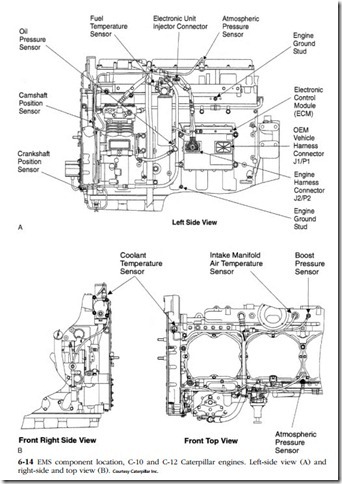
are outlined in Table 6-2. Figure 6-14 shows the location of EMS components on the C-10 and C-12 engines. Sensor location is similar for the C-15, except that boost and intake-manifold pressure sensors are on the left side forward rather than on the right.
Electronic unit injector
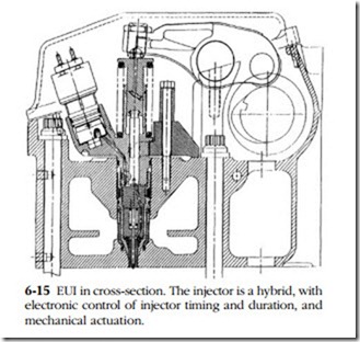
Both the 3100-3500 and C series engines employ EUIs that combine mechanical actuation with electronic control over fuel volume. Figure 6-15 illustrates an EUI in cross-section. A roller-tipped rocker arm, acting on in the injector plunger, provides the force necessary to generate the 28,000-psi injection pressure. The solenoid valve, shown on the left of the drawing, opens the spill/fill port to admit fuel into the injector barrel during the period of plunger retraction. A spring-loaded check valve, located near the injector tip and set to open at 5000 psi, remains closed during the fill process.
Injection can be initiated any time after the plunger starts its downward travel. But until the ECM signals the solenoid valve to close the spill/fill port, fuel merely cycles through the EUIs as a coolant and as a purge to remove any entrapped air.
Upon signal, the solenoid valve closes the port, trapping fuel in the injector barrel. Further downward movement of the plunger raises fuel pressure sufficiently to over- come spring tension acting on the check valve. The check valve opens and injection begins.
Injection continues until the ECM signals the solenoid to open the spill/fill port. Responding to the sudden loss of pressure at the injector tip, the check valve snaps shut. Injection ceases. The plunger continues its downward stroke, displacing fuel through the open spill/fill port and into the fuel-return gallery.
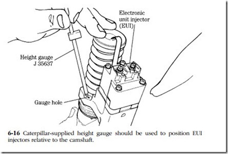
Although the software has primary responsibility for injector timing, plunger movement is affected by rocker-arm lash. The onset of pressure rise depends upon the clearance between the rocker arm and the plunger. A Caterpillar PN J 35637 height gauge is used to establish this critical variable (Fig. 6-16).
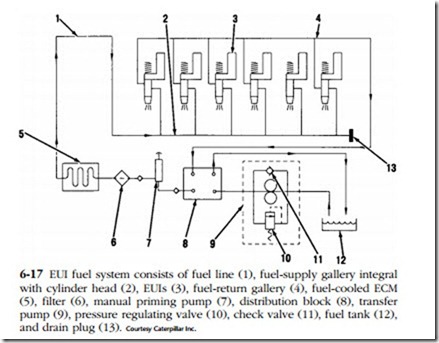
pump (9), pressure regulating valve (10), check valve (11), fuel tank (12), and drain plug (13). Courtesy Caterpillar Inc.
Low-pressure circuit
Figure 6-17 illustrates the low pressure circuit for EUI-equipped engines. A gear-type transfer pump (9) delivers fuel from the tank (12) to the injectors (3). The pump incorporates a check valve (11) that permits fuel to flow around it during manual priming and a pressure-relief valve (10) to protect the system from over-pressurization.
Cat supplies dealer mechanics with a special tool, consisting of a pressure gauge, a sight glass, and the necessary fittings for makeup to mechanical and electronic low- pressure systems. This tool is similar to the Ford tool described in Chap. 4.
Check fuel pressure by removing the fuel pressure sensor at the base of the fuel filter. Install a pressure gauge and run the engine at rated rpm and load. Pressure should be 90 psi. If pressure is 75 psi or lower, check the fuel level in the tank, verify that the fuel cap vent is open, and that supply and return lines are in good condition. Pay particular attention to the return line, which can collapse if exposed to excessive heat. Replace the fuel filter. If necessary, replace the lift pump.
If fuel pressure is high, that is, 100 psi or greater, remove the fuel-regulating valve (10) and make sure the orifices near the tip of the unit are open. Flush out any debris and attempt to find the source of the contamination. Check for a clogged fuel- return line. Verify that the transfer-pump relief valve functions.
High-pressure circuit
Deactivating one EUI at a time will identify misfiring or dead cylinders. As mentioned previously, current values are high, and for your own safety, do not tamper with EUI wiring while the engine is running. Professional-quality scanners can safely deny power to the injectors so that the effect, if any, on engine performance can be gauged. When a weak cylinder is located, replace the injector and retest. If a new injector does not solve the problem, check valve lash to make certain that the valves are seating and, if necessary, make a cylinder compression as described in Chap. 4. Caterpillar technicians use a boroscope, inserted through the injector mounting boss, to visually inspect cylinder internals.
Hydraulic/electronic unit injector
HEUI evolved from the EUI, and since mid-1994 has been used on Caterpillar, International T444E, DT466E, 1530E, certain Perkins models, and, most famously, on the Ford (International) Power Stroke. Unlike conventional camshaft-driven unit injectors, HEUIs are actuated by high-pressure crankcase oil. Since injection is no longer tied to camshaft motion, fuel can be injected at any crank angle. At higher-than-idle speeds, injector pressure is independent of engine rpm and can attain values of 30,000 psi.
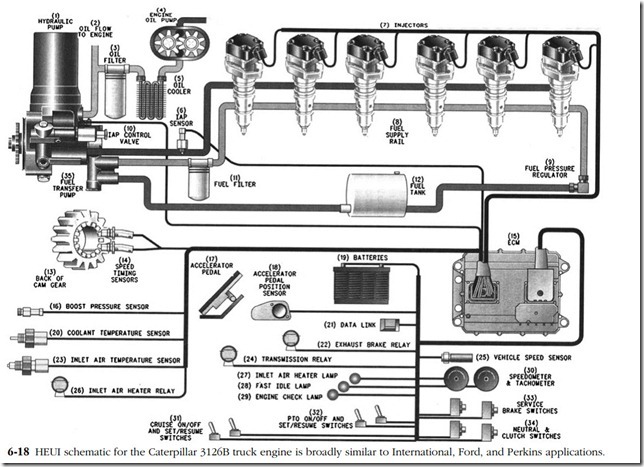
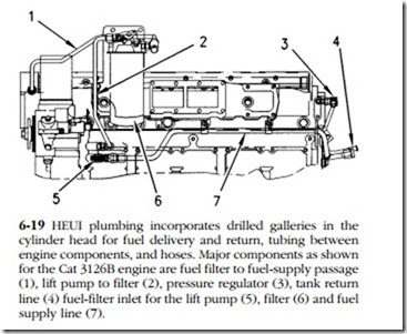
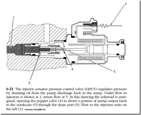
Figure 6-18 illustrates the general layout of the Cat system that differs only in detail from Ford and other HEUI applications. Figure 6-19 shows the arrangement of the piping for the 3126B truck engine, which is the focus of this discussion. The high-pressure oil pump delivers crankcase oil to the injectors at cranking pressures of 500 psi that increase to as much as 3300 psi under speed and load. The computer-controlled injector actuation pressure control valve (IAPCV) regulates oil pressure by shunting pump output to the crankcase. Fuel pressure is regulated to 55 psi minimum.
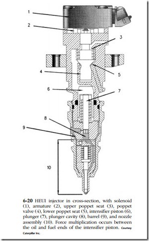
HEUI consists of five major components—a solenoid, poppet valve, mushroom- shaped intensifier piston, barrel, and a seven-hole nozzle assembly (Fig. 6-20). Approximately 4A is required to energize the solenoid and 1.5A holds it open.
Upon command, the solenoid opens the poppet valve to admit high-pressure lube oil to the upper end of the intensifier piston (6 in Fig. 6-20). The oil forces the piston and plunger (7) down against fuel trapped in the injector body by a ball check valve. The fuel end of the plunger is smaller in diameter than the upper, or oil, end. The difference in cross-sectional area multiplies the hydraulic force acting on the fuel times, to produce injection pressures of 3000–30,000 psi. Pressurized fuel lifts a second check valve, enters the cavity on the lower right of the drawing, and reacts against the needle shoulder to overcome spring tension. Nozzle-opening pressure (NOP) varies with the application. Some Cat injectors have an NOP of 4500 psi. Rebuilders of Power Stroke HEUIs look for 2750 +/_ 75 psi.
Note that both band width (the time the injector is open) and actuator-oil pressure determine the amount of fuel delivery.
HEUI injectors have undergone constant refinement. The most significant change is the split-shot PRIME (preinjection metering) version that first appeared on 1994 California Ford F series trucks and has since become almost universal.
These injectors work like other HEUIs, except that the plunger incorporates a radial groove that receives fuel through six bleed ports drilled in the face of the plunger. As the piston moves downward, the groove aligns with a spill port in the barrel, shunting pressure. The output-side check ball seats and injection stops. Further piston movement masks the port and injection resumes.
Injector service
The three external o-rings are critical. The upper o-ring, now supplied with steel and elastomer backup rings, prevents lube oil from leaking up and out of the injector
body. The middle o-ring and its supporting rings prevents lube oil from mixing with the fuel. Sudden and dramatic increases in oil consumption can usually be attributed to failure of this middle ring assembly. The lower o-ring keeps fuel from puddling around the base of the injector.
Lubricate o-rings and wait ten minutes or so for the rings to assume their natural shape before installing injectors or other parts sealed by o-rings. Failure to do so can result in leaks. Seals on all plumbing, especially the fuel-return lines, are critical. Do not disturb connections without new seals in hand.
Injector failure is not always easy to diagnose, since rough idle, long cranking periods, and misfires at particular rpm’s can have multiple causes, several associated with the high-pressure lube oil system. This subject is explored in more detail in the con- text of Power Stroke systems. It can be helpful to check individual exhaust runner temperatures with an infrared thermometer. All exhaust-manifold runners should be at or very close to the same temperature: a hotter-than-average runner indicates the associated cylinder is receiving too much fuel, and a cool runner means insufficient fuel. Both of these conditions point to injector failure.
HEUI injectors are not field repairable in the sense that the average mechanic can do the work. Rebuilt units are available from factory and independent suppliers such as Dipaco.
HEUI hydraulics
A seven-piston swash-plate pump, located forward on the left side of the 3126B engine, supplies oil pressure to the injectors through a passage in the engine cylinder head. Oil returns to the sump through ports under the valve cover. The pump, also used by Ford and International, is nonrebuildable.
The injector actuation pressure control valve (IAPCV), mounted aft of the pump, regulates oil pressure (Fig. 6-21). The poppet valve floats in suspension between pump-discharge pressure that tends to move it to the left and force generated by the solenoid that pushes it to the right. When the oil pressure over-balances the solenoid, the poppet valve opens to shunt a portion of pump output back to the crankcase. Pressure falls.
How much force the solenoid generates depends upon the amount of current it receives. The ECM compares oil-pressure data, collected 67 times a second from a
sensor mounted in the cylinder-head gallery, with desired pressure and adjusts cur- rent intensity accordingly.
Note that HEUI injectors in this application require 870 psi to fire, a figure that varies with ambient temperature. The engine will not start unless firing pressure is reached. Pressure ranges between 580 psi during initial cranking to 3350 psi with 3500 psi occasionally seen.
When the IAPCV fails, replacing the o-rings can sometimes save the cost of a new part. One should be very careful when servicing these valves, since wrench torque can easily distort the housing. Caterpillar supplies a special tool for this purpose, which can be described as a flair-nut crow’s-foot wrench. That is, the box end of the wrench has been partially cut away so that it will slip over the valve body. Torque to 37 ft-lb.
Fuel pressure
The piston-type transfer pump runs off an eccentric on the back of the injector oil pump. Nominal fuel pressure is 65 psi at the pump. When the measurement is made downstream of a new filter, expect to see a pressure drop of about 5 psi. If pressures are low, clean the inlet screen on the pump and replace the fuel pressure regulator with a known-good unit. If the problem persists, replace the transfer pump.
Boost pressure
The amount of boost relative to engine speed and load depends upon the application, with the specification given for 28.8 in./Hg dry barometric pressure, 77°F (25°C) ambient temperature, and 35 API gravity fuel. If the air is denser, that is, if barometric pressure is higher and/or temperature lower, boost pressure will be higher than specified. Likewise, a heavier fuel increases turbo output. When docu- mentation is unavailable, consult the factory for boost specifications. The wastegate is nonadjustable.
Low manifold pressure combined with high exhaust temperature suggests that the air filter is clogged or that the aftercooler, pressure-side turbo plumbing, or intake-manifold gasket leak.
Throttle position sensor
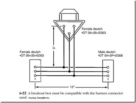
The TPS is located under the accelerator pedal and generates a pulse-width signal that can read with a Fluke Model 97 or equivalent multimeter and a breakout box. The breakout consists of three 12-in. long No.10 AWG wires that bridge the harness connectors and three 6-in. long No. 12 AWG wires that make up to the meter.
1. Using Caterpillar PN 1U5804, crimp Deutch DT 04-3P-E008 male connectors to one end of each of the three long wires and DT 04-3P-E003 female con- nectors to the other ends. See Fig. 6-22.
2. Make up DT 04-3P-E003 female connectors to one end of each of three short wires. These connectors plug into the meter receptacle.
3. Solder the three short wires to the centers of the longer wires.
Set the meter to measure pulse-width percentage and, with the ignition switch “on,” depress the accelerator pedal. Pulse width varies with make and model, but should be in the neighborhood of 80–90% at wide-open throttle and drop to 10 or 20% with the pedal at rest. A spare TPS is good insurance.
Female deutch
•DT 06–35–E003
•DT 06–35–E003
Male deutch
•DT 04–3P–E008
Trouble codes
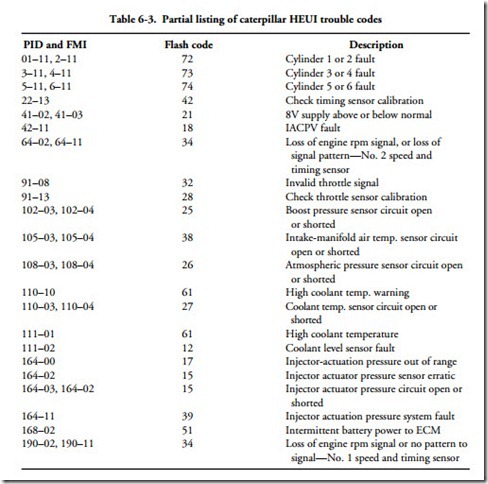
Table 6-3 lists the most critical DTCs for this system. PID (parameter identifier) is a two- or three-digit SAE numerical code assigned to each component. For example, 91 refers to the throttle position sensor. FMI is a failure mode identifier used to describe the kind of failure detected, and flash refers to the number of blinks the code triggers on the “check engine” lamp. Some codes are merely informational and do not affect engine performance. Active codes, that is, those that turn on the diagnostic lamp and keep it on, mean that the problem requires immediate attention. The lamp will go out when the malfunction is repaired. Intermittent malfunctions, often caused by loose harness connectors or bad grounds, cause the lamp to blink and go out. These codes are then logged in computer memory, where they can be retrieved and erased with the appropriate scanner. Intermittent codes that are logged repeat- edly need investigation.
