This chapter describes the operation of four popular engine management systems (EMS)—Bosch, Caterpillar, Ford Power Stroke, and Detroit Diesel. The workings of the onboard computer, electronic injectors, and other key components are discussed, together with basic troubleshooting and some repair procedures. But readers should understand that this material is merely an introduction to these complex systems and that it does not substitute for factory documentation and training.
Background
Before we get down to the nitty-gritty of repair and troubleshooting of specific systems, it is helpful to take a brief look at how electronics have transformed the diesel engine from an industrial workhorse to power for luxury automobiles. Most of this work was done in Europe and primarily by Robert Bosch GmbH.
Modern common-rail systems
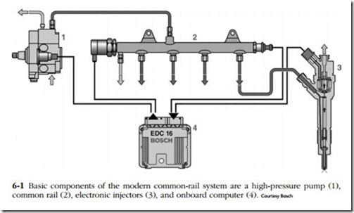
Since the 1960s, engineers realized that an updated common-rail system, using computer-controlled injectors and ultra-high fuel pressures, offered revolutionary possibilities for the diesel engine. As shown in Fig. 6-1, the modern c-r system employs a remote pump to pressurize a fuel rail, which functions both as a reservoir and as an accumulator. The rail expands to dampen pump pressure peaks and contracts to stabilize pressure when the injectors open. Since rail pressure is almost constant, fuel can be injected at will, independent of pump plunger movement. When coupled with split- shot electronic injectors, fuel delivery begins early during compression stroke and can be initiated after combustion to light-off carburized particulate traps. In other words, common-rail was an enabling technology for electronic fuel injection.
Hino Rising Ranger trucks. Meanwhile Fiat and its subsidiary Magneti Marelli Power Trains were working on c-r for passenger cars and light trucks. By the late 1990s, the prototype was turned over to Robert Bosch GmbH for production. The first- generation 1350-bar (1 bar = 14.51 psi) Bosch c-r system made its debut in 1997 on Alfa Romeo and Mercedes-Benz high-speed touring cars.
Subsequent Bosch developments were rapid:
• 1999—First generation, truck 1480-bar system (Renault).
• 2001—Second generation, passenger-car 1600-bar system (Volvo and BMW).
• 2002—Second generation, truck 1600-bar system (MAN).
• 2003—Third generation, passenger-car 1600-bar system (Audi V-6). Piezo injectors reduced emissions by 20%, boosted power 5%, reduced fuel con- sumption 3%, and engine noise by 3 dB(A).
• 2006—Fourth generation under development with higher pressures and revised injector geometry.
Since the common rail is not protected by patent (low-pressure versions have been around since the 1920s), the technology has become nearly universal for auto- motive and light truck engines, manufactured by companies as diverse as Hyundai, Cummins, and Mercedes-Benz. Nor is c-r limited to automotive applications: L’Orange GmbH has prototyped a c-r upgrade for marine engines with cylinder bores as large as 500 mm, and Cummins will soon release a common-rail kit for retrofit to locomotives.
Solenoid-actuated injectors
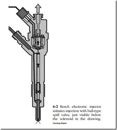
Figure 6-2 is a schematic of a multi-hole, solenoid-operated injector of the type used on common-rail systems. The upper end of the spring-loaded needle is flat and the large-diameter lower end is shouldered. Hydraulic pressure applied to the flat
tends to push the needle down, while pressure bearing against the shoulder would raise it. Movement depends upon the balance of pressures acting on these surfaces and upon spring tension.
A ball-type spill valve stands between high-pressure fuel from the rail and the low-pressure circuit that returns fuel to the tank. When at rest, the solenoid is not energized and the armature spring holds the ball valve closed. No fuel flows to the tank, but both needle working surfaces see the same high pressure. The forces generated—lift from the shoulder and down-force from the flattened top—neutralize each other and spring tension keeps the needle seated.
When the solenoid is energized, the armature retracts and the ball valve opens to the low-pressure return line. Because the orifice is quite small, most of the pres- sure drop is confined to the area above the valve. Pressure in the nozzle cavity remains high. This pressure lifts the needle to commence injection. When de- energized, the solenoid closes the ball valve, pressures equalize and the spring forces the needle down to end injection.
Even though hydraulics do the heavy work, solenoids require large amounts of electric power. To overcome armature inertia, the drag of heavy fuel, and other oper- ating variables, Bosch solenoids receive a 50V, 20A jolt during the opening phase. Once the armature is retracted, battery voltage holds it in place.
Suspect injectors must be farmed out to specialists for cleaning, repair, and re- calibration.
Piezo-actuated injectors
Piezo injectors evolved from the flow-control technology developed by Siemens VDO for ink jet printers. Piezo crystals expand when excited by voltage and, con- versely, generate voltage when compressed. The latter feature is used in cigarette and barbecue-pit lighters.
The growth of piezo crystals under voltage is miniscule: a single wafer 80 µm thick elongates about 0.1 µm at 160V. Siemens stacks the wafers to produce a stroke of about 40 µm that is hydraulically amplified to unseat the spill valve. The wafer pack responds within 80 milliseconds of excitation, or three times faster than the best solenoids, and with an actuation delay an order of magnitude faster. As a result, injection can be divided into as many as seven precisely metered shots, each accu- rate to within less than a milligram of fuel. This translates into 3% more power and 15% better fuel economy than solenoids offer, and the ability to meet Euro 4 stan- dards without particulate traps.
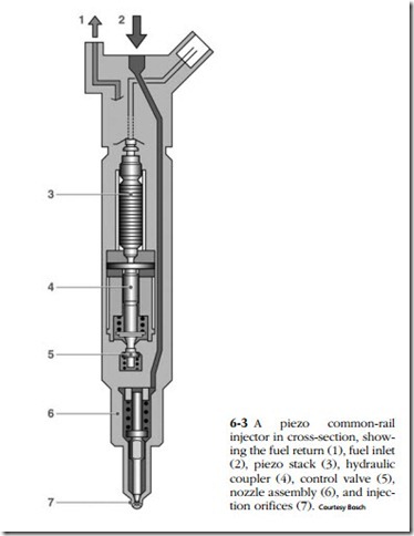
These injectors run on the same high-pressure regime as solenoid types: piezo- actuated common-rail injectors, like the one shown in Fig. 6-3, see peak pressures of around 1600 bar, a figure that will be increased to 2000 bar in the next generation. Piezo unit injectors develop pressures in excess of 2000 bar. Depending upon the application, injector tips have as many as 10 orifices with diameters of less than 0.1 mm.
To date Siemens has built more than 15 million c-r injectors, used on upscale vehicles such as the Audi, Mercedes, Land Rover, Jaguar, and the 2007 Mercedes E320, which will introduce the technology to the North American market. Siemens also manufactures piezo unit injectors for VW and International. The latter operation is based in Blythewood, South Carolina, with all production going to the American diesel maker.
Solenoid injectors from Bosch, Denso, and Delphi continue to find buyers since they cost half as much as the Siemens version and meet current emission standards. Most observers believe that solenoids will hold their market share among low-end car makers until 2010 when Euro 5 standards come into effect.
Figure 6-3 shows a piezo injector in cutaway view. Wafer expansion opens a servo valve that stands between the high-pressure fuel delivery circuit and the low- pressure return. With the valve open, pressure above the needle diminishes, while pressure in the nozzle cavity remains nearly constant. The differential unseats the needle to initiate injection.
Because wafer expansion is so miniscule, a hydraulic coupler is used to extend the stroke. The coupler also functions like a hydraulic valve lifter to compensate for lash caused by thermal expansion.
Service
While injectors are routinely replaced in the field, it should be noted that each injector is marked with a code, showing where it falls within production tolerances. For best performance, the code must be inputted into the EMS with a factory- supplied scan tool.
Unit injection
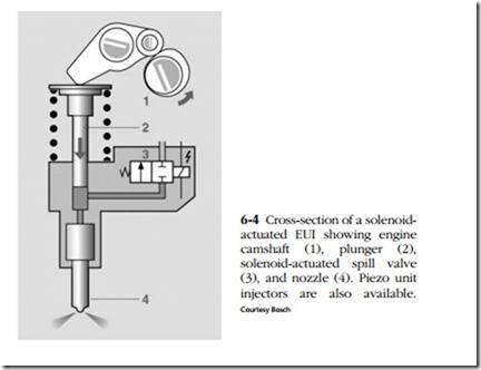
While common rail is standard on most European auto and light-truck engines, Volkswagen remains committed to electronic unit injection. Figure 6-4 illustrates the Bosch unit injector of the type currently used by VW and its SEAT and Skoda affiliates. A solenoid-actuated valve controls injector timing and duration, which of course, must occur during periods when the UI is pressurized by the camshaft. Caterpillar and Detroit Diesel developed their own versions of electronic unit injec- tors (EUIs) described below.
In summary, computer-controlled c-r and unit-injector (UI) systems came about because of the need to reduce exhaust emissions by providing more precise control over fueling. Secondary effects are higher power outputs, more flexible torque curves, and better fuel economy.


