Electrical Switchgear and Circuit Breakers
The DC testing of electrical switchgear and circuit breakers involves the following:
• Insulation resistance measurement test
• DC hi-pot test
• Circuit breaker contact resistance test
The insulation resistance measurement test may be conducted on all types of electrical switchgear and circuit breakers using the insulation resistance megohmmeter commonly known as the Megger.
Insulation Resistance Measurement Test
The insulation resistance test consists of applying voltage (500–15,000 V DC) to the apparatus to determine the megohm value of resistance. This test does not indicate the quality of primary insulation. Several factors should be remembered when performing this test. The first is that this test can indicate low values of insulation resistance because of many parallel paths. The other is that an insulation system having low dielectric strength may indicate high
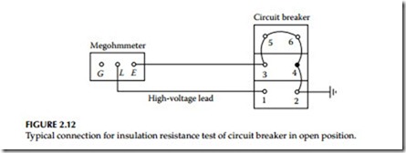
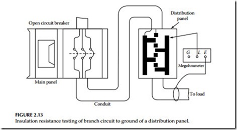
resistance values. In view of this, the test results should only be interpreted for comparative purposes. This does not indicate the quality of the primary insulation system with regard to the dielectric strength to withstand high voltages. The connection diagram for making this test on a power circuit breaker is shown in Figure 2.12. The connection diagram for testing the insulation resistance of each branch circuit in a distribution panel is shown in Figure 2.13. When performing insulation testing, it is recommended that auxiliary equipment, such as potential transformers and lightning arresters, be isolated from the stationary switchgear.
Insulation resistance tests are made with the circuit breaker in open and closed position, whereas the insulation test for the switchgear bus is made with one phase to ground at a time, with the other two phases grounded. The procedure for this test is as follows:
• Circuit breaker open:
Connect high-voltage lead to pole 1. Ground or guard all other poles. Repeat for poles 2 through 6, in turn, with other poles grounded.
• Circuit breaker closed:
Connect high-voltage lead to pole 1, with either pole of phase 2 and 3 grounded. Repeat for phases 2 and 3 with other phases grounded.
• Stationary gear (buses):
Connect high-voltage lead to phase 1 with phases 2 and 3 grounded or guarded. Repeat the same for phases 2 and 3 with other phases grounded. Repeat this test for checking the insulation resistance between phase 1 to 2, phase 2 to 3, and phase 3 to 1.
In the case of outdoor oil circuit breaker bushings, experience has shown that any bushing, with its assembled associated insulating members, should, for reliable operation, have an insulation resistance value above 10,000 MΩ at 20°C. This assumes that the oil within the tank is in good condition, that the breaker is separated from its external connections to other equipment, and that the porcelain weather shield is guarded. This means that each component such as the stripped bushing itself, cross-member, lift rod, lower arcing shield, etc. should have an insulation resistance in excess of that value.
Any components that are superficially clean and dry and have values less than 10,000 MΩ are usually deteriorated internally, by the presence of mois-
ture or carbonized paths, to such an extent that they are not reliable for good service unless reconditioned. This is particularly so when operating under surge conditions such as during lightning disturbances. In the case of the stripped bushing itself, the lower stem and upper weather shield must be either perfectly clean or guarded before it is condemned as unreliable because of an insulation resistance value less than 10,000 MΩ.
Since bushings and other associated members have very high insulation resistance values normally, a megohmmeter insulation tester having a range of at least 10,000 MΩ is necessary to test such equipment. Megohmmeter instru- ments having ranges up to 50,000 MΩ will permit observation of deteriorating trends in bushings before they reach the questionable value of 10,000 MΩ.
DC High-Potential Test
The hi-pot testing of switchgear involves testing of the circuit breakers and switchgear buses separately. This is a major test and determines the condition of the insulation of the switchgear assembly. The DC hi-pot test is not preferred for testing AC switchgear because the application of DC voltage does not pro- duce similar stress in the insulation system as is produced under operating conditions. Moreover, the DC hi-pot test produces corona and tracking owing to concentration of stress at sharp edges or endpoints of buses. The corona and tracking are more pronounced in older equipment, and it is therefore recommended that DC hi-pot testing be avoided on such equipment.
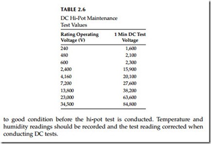
The test procedures for DC hi-pot testing are similar to those of AC hi-pot testing. If DC hi-pot testing is to be performed, the DC voltage test values shown in Table 2.6 are recommended for various voltage-class equipment.
The hi-pot test should be conducted under conditions similar to those of commercial testing. The switchgear should be wiped, cleaned, and restored
Circuit Breaker Contact Resistance Measurement Test
Stationary and moving contacts are built from materials that provide good resistance to arcing. However, if contacts are not maintained on a regular basis, resistance due to repeated arcing builds up resulting in the contacts ability to carry current. Excessive corrosion of contacts is detrimental to the breaker performance. One way to check contacts is to apply DC current and measure the contact resistance or voltage drop across the closed contacts.
The breaker contact resistance should be measured from bushing terminal to bushing terminal with the breaker in closed position. It is recommended that for medium and high voltages the resistance test be made with a micro- ohmmeter having at least 100 A DC output. The use of a higher current value gives more reliable results than using lower current values. The resistance value is usually measured in micro-ohms (μΩ).


