Capacitor Ratings
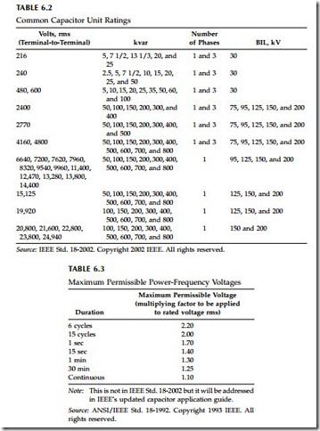
Capacitor units rated from 50 to over 500 kvar are available; Table 6.2 shows common capacitor unit ratings. A capacitor’s rated kvar is the kvar at rated voltage. Three-phase capacitor banks are normally referred to by the total kvar on all three phases. Distribution feeder banks normally have one or two or (more rarely) three units per phase. Many common size banks only have one capacitor unit per phase.
IEEE Std. 18 defines standards for capacitors and provides application guidelines. Capacitors should not be applied when any of the following limits are exceeded (IEEE Std. 18-2002):
• 135% of nameplate kvar
• 110% of rated rms voltage, and crest voltage not exceeding 1.2 2
of rated rms voltage, including harmonics but excluding transients
• 135% of nominal rms current based on rated kvar and rated voltage
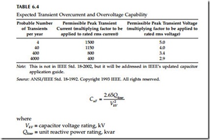
Capacitor dielectrics must withstand high voltage stresses during normal operation — on the order of 2000 V/mil. Capacitors are designed to with- stand overvoltages for short periods of time. IEEE Std. 18-1992 allows up to 300 power-frequency overvoltages within the time durations in Table 6.3 (without transients or harmonic content). New capacitors are tested with at least a 10-sec overvoltage, either a dc-test voltage of 4.3 times rated rms or an ac voltage of twice the rated rms voltage (IEEE Std. 18-2002).
Source: ANSI/IEEE Std. 18-1992. Copyright 1993 IEEE. All rights reserved.
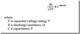
Capacitors should withstand various peak voltage and current transients; the allowable peak depends on the number of transients expected per year (see Table 6.4).
Capacitors are made within a given tolerance. The IEEE standard allows reactive power to range between 100 and 110% when applied at rated sinusoidal voltage and frequency (at 25˚C case and internal temperature) (IEEE Std. 18-2002). Older units were allowed to range up to 115% (ANSI/IEEE Std. 18-1992). Therefore, the capacitance also must be between 100 and 110% of the value calculated at rated kvar and voltage. In practice, most units are from +0.5 to +4.0%, and a given batch is normally very uniform.
Capacitor losses are typically on the order of 0.07 to 0.15 W/kvar at nominal frequency. Losses include resistive losses in the foil, dielectric losses, and losses in the internal discharge resistor.
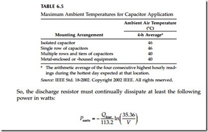
Capacitors must have an internal resistor that discharges a capacitor to 50 V or less within 5 min when the capacitor is charged to the peak of its rated voltage ( 2Vrms ) . This resistor is the major component of losses within a capacitor. The resistor must be low enough such that the RC time constant causes it to decay in 300 sec as
Some utilities use a shorting bar across the terminals of capacitors during shipping and in storage. The standard recommends waiting for 5 min to allow the capacitor to discharge through the internal resistor.
Capacitors have very low losses, so they run very cool. But capacitors are very sensitive to temperature and are rated for lower temperatures than other power system equipment such as cables or transformers. Capacitors do not have load cycles like transformers; they are always at full load. Also, capacitors are designed to operate at high dielectric stresses, so they have less margin for degraded insulation. Standards specify an upper limit for application of 40 or 46°C depending on arrangement (see Table 6.5). These limits assume unrestricted ventilation and direct sunlight. At the lower end, IEEE standard 18 specifies that capacitors shall be able to operate continu- ously in a –40˚C ambient.


