Loss and Thermal Performances
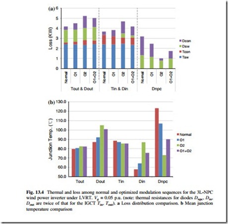
The loss distributions of the 3L-NPC wind power converter under LVRT when utilizing the optimized vector sequences O1, O2, and O1 + O2 (enabling the NP potential control ability) are compared in Fig. 13.4a, where Dcon and Tcon are the conduction loss in diode and IGCT, respectively, Dsw and Tsw are the switching loss in diode and IGCT, respectively. The comparison of thermal distribution is shown in Fig. 13.4b. It can be seen that, both of the optimized sequences O1 and O2 achieve the loss and thermal transferring from NPC diodes to other power devices, and sequence O2 shows the best thermal distribution performance because of the eliminated zero voltage level at maximum phase current. When alternating the sequences O1 and O2 in neighboring switching cycles to enable the NP
potential control ability, the loss and thermal performances are a tradeoff between the sequences O1 and O2.
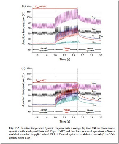
The dynamic thermal performance of 3L-NPC wind power inverter which goes from normal operation to extreme LVRT can be also simulated. The process is conducted as follows: the inverter is first operating under the normal grid voltage with normal modulation method, and the wind speed is set as 8 m/s with 3.2 MW output active power. Then the grid voltage dips to 0.05 p.u. for 500 ms, during this period both normal and optimized modulation methods are applied, respectively.
Afterwards the grid voltage recovers back to the normal operation status before the LVRT. The junction temperature of each power device when applying different modulation methods are shown in Fig. 13.4b, due to the effect of thermal capacitances, the junction temperature of each power device fluctuates with fundamental frequency.
As it can be seen, before the LVRT (simulation time 2 s), Dnpc is the most stressed device with 90 °C maximum junction temperature and 9 K temperature fluctuation amplitude. When LVRT is presented and normal modulation method is still applied, as shown in Fig. 13.5a, the maximum junction temperature in Dnpc significantly rise to 108 °C with 18 K fluctuation at the end of LVRT (simulation time 2.5 s). If the O1 + O2 optimized modulation method is applied, as shown in Fig. 13.5b, the maximum junction temperature in Dnpc keeps nearly unchanged and it is reduced by 22 with 8 K less fluctuation compared to the normal modulation. The junction temperature reduction may contribute to a lifetime extension of the converter according to, e.g., the well-known Coffin-Masson lifetime model.

