Timed Controlled Starting
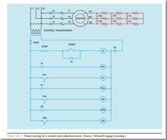
Another method of starting a wound rotor motor is with the use of time delay relays. Any number of steps can be employed, depending on the needs of the driven machine. A circuit with four steps of starting is shown in Figure 44 – 7. In the circuit shown, when the START button is pressed, motor starter M energizes and closes all M contacts. The load contacts connect the stator winding to the power line. At this point in time, all resistance is connected in the rotor circuit, and the motor starts in its lowest speed. When the M auxiliary
contacts close, timer TR1 begins its time sequence. At the end of the time period, timed contact TR1 closes and energizes the coil of contactor S1. This causes the S1 load contacts to close and short out the first bank of resistors in the rotor circuit. The motor now accelerates to the second speed. The S1 auxiliary contact starts the operation of timer TR2. At the end of the time period, timed contact TR2 closes and energizes contactor S2. This causes the S2 load contacts to close and shunt out the second bank of resistors. The motor accelerates to third speed. The process continues until all the resistors have been shorted out of the circuit and the motor operates at the full speed.
The circuit shown in Figure 44 – 7 is a starter circuit in that the speed of the motor cannot be controlled by permitting resistance to remain in the circuit. Each time the START button is pressed, the motor accelerates through each step of speed until it reaches full speed.
Starting circuits generally employ resistors of a lower wattage value than circuits that are intended for speed control, because the resistors are used for only a short period of time when the motor is started. Controllers must employ resistors that have a high enough wattage rating to remain in the circuit at all times.

