VARYING THE VOLTAGE ALONG WITH FREQUENCY
Whenever variable-frequency speed control is mployed, the motor supply voltage
cannot be allowed to remain at a steady value. The magnitude of the motor voltage
must be increased or decreased in proportion to the frequency. That is. the voltageto-
frequency ratio, Vlf. must remain constant (approximately).
For instance, if the motor has a nameplate rating of 240 V at 60 Hz, the
voltage-to-frequency ratio is 4 (240 -^ 60 = 4). If the motor is speeded up by
adjusting its variable-frequency inverter to, say, 90 Hz, the voltage magnitude must
be increased to 360 V. since 4 x 90 = 360. If the motor is slowed down by adjusting
the inverter frequency to 45 Hz, the voltage magnitude must be decreased to
180 V, since 4 x 45 = 180.
Here is the reason it is necessary to maintain a constant K// ratio: The stator’s
magnetic field strength must remain constant under all operating conditions. If the
stator field strength should happen to rise much above the design value, the motor’s
core material would go into magnetic saturation. This would effectively lower the
core’s permeability, thereby inhibiting proper induction of voltage and current in
the rotor loops (or bars), thus detracting from the motor’s torque-producing capability.
On the other hand, if the stator field strength should happen to fall much
below the design value, the weakened magnetic field would simply induce lower
values of voltage and current in the rotor loops, in accordance with Faraday’s law.
This likewise would detract from the motor’s torque-producing ability.
So the sinusoidal magnetic field produced by the stator windings must hold
a constant rms value, regardless of frequency. But what determines the value of
the stator’s magnetic field? The stator’s magnetizing current, that’s what. The
magnetizing current of an induction motor is the current that flows through the
stator winding when the rotor is spinning at steady-state speed with no torque load;
this is in the same way that the magnetizing current of a stationary transformer is
the current that flows through the primary winding when the secondary winding is
operating under no electrical load. Just as for a stationary transformer, the magnetizing
current for an induction motor is given by Ohm’s law.
where V is the rms value of the applied stator voltage and X^^ is the inductive
reactance of the stator winding.*
In Eq. ( 15-5), Jf; does not remain constant as the supply frequency is adjusted;
it varies in proportion to the frequency (Xi^ = lirfL). Therefore V must also be
varied in proportion to the frequency, so that the Ohm’s law division operation
yields an unvarying value of magnetizing current.
Alternatively, using X^ = 2-it/L, we can rewrite Eq. (15-5) as
We are neglecting the resistance of the motor winding, assuming that its impedance is wholly
reactive. This is a reasonable assumption for motors above the fractional-horsepower range.
In Eq. ( 15-6), the factor l/Z-irL is a constant, determined by the motor’s construction
details that have a bearing on the inductance of the stator winding. Equation (15-
6) makes it plain that a constant /,n_,j, can be achieved only by maintaining a constant
I/// ratio.
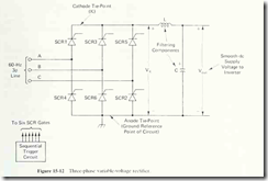
The most convenient circuit for producing a high-power variable dc voltage
to drive the inverter of Fig. 15-9(a) is a three-phase six-pulse variable rectifier built
with six SCRs. Figure 15-12 is a schematic diagram of such a rectifier.
The trigger circuit in Fig. 15-12 delivers line-synchronized gate pulses to the
six SCRs sequentially. Because the gate pulses are line-synchronized, the pulse
rate is not variable; six equal-interval pulses occur during every cycle of the 6()-Hz
ac line, one pulse every 2.78 milliseconds. However, the trigger circuit can vary
the delay angle of the pulses, with the delay angle referenced to the £ ,,; line voltage
of Fig. 15-13(a). That is, the trigger circuit can deliver gate pulses according to
either schedule 1 or schedule 2, as follows:
1. Deliver one gate pulse at the instant £4^ makes a positive-going zero crossover;
deliver the next gate pulse when £^g is 60° into its cycle; deliver the
next gate pulse when £,/j is 120° into its cycle; and so on. This schedule is
depicted in Fig. 15-13(b).
2. Deliver one gate pulse 30° after Ey^g makes a positive-going zero crossover;
deliver the next gate pulse when £4^ is 90° into its cycle (60° after the previous
gate pulse); deliver the next gate pulse when Ej,g is 150° into its cycle (again,
60° after the previous gate pulse); and so on. This schedule is depicted in Fig.
15-13(c).
Schedule 1 corresponds to a delay angle of zero and schedule 2 corresponds
to a delay angle of 30°. Actually, the delay angle is continuously variable over the
range from 0° to 90° by the trigger circuit in Fig. 15-12. As the delay angle is varied,
the average value of the V,^ waveform varies along with it. In that figure, voltage
Kji.- appears between the cathode tie-point and the anode tie-point. The LC lowpass
filter removes the ac content of the V^^ waveform, and delivers a smooth dc
voltage to the output terminals of the rectifier. The magnitude of V^^^,, is equal to
the average value of the six-pulse-per-cycle Vf^ waveform.
