MOTOR BEARING CURRENTS
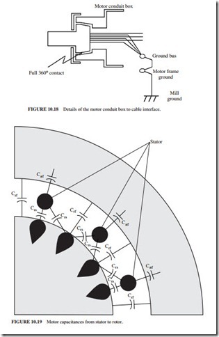
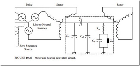
These currents flow through the motor bearings due to the transient switching voltages. Figure 10.19 illustrates the capacitances from all points on the stator windings to all points on the rotor. The total current flowing in the bearing is the sum of the current flowing through the capacitances due to the voltage transients (I C dV/dt) and the current gener- ated due to the common-mode voltage (Fig. 10.20). The latter current is generated due to the nonsymmetric switching pattern in the device. It is usually much larger than the first. The total current flowing through the bearing can be significant. It causes pitting on the run- ning surfaces.
Figure 10.20 illustrates the equivalent circuit of the capacitance shown in Fig. 10.19. And Rb, Cb, and Zb are the components of the bearing model. The common-mode voltage that is generated by the nonsymmetry in the switching pattern within the inverter is called the zero sequence source.
The bearing makes relatively good contact with the races during low-speed operation. Therefore, it is able to conduct substantial currents without incurring damage. At higher speeds, the bearing starts to operate on a thin film of oil (called hydroplaning). It is only a few micrometers thick and acts as both an insulator and a capacitor (Cb in Fig. 10.20). When the shaft voltage becomes very large and the oil-film capacitor breaks down, a high electrostatic discharge current (ESD) flows from the bearing to the race through Zb. The ESD will eventually destroy the bearings.
The bearing currents must be eliminated or bypassed around the bearings. Otherwise, the bearing life will be very short. If insulation was placed on the motor bearings (in an attempt to stop the bearing current flow), the current will return to ground through the bear- ings of the attached machine (e.g., pump, compressor, etc.). These bearings, which are nor- mally larger and more expensive than the motor bearings, will be destroyed.
The following techniques can be used to mitigate the problem with bearing current:
Add a Motor Shaft Grounding Brush
A conductive grounding brush can be attached to the motor frame. It rubs on a machined area of the motor shaft. In theory, most of the current should be shunted around the bear- ing directly to the motor frame.
These are the problems encountered with the solution:
1. The brushes are mounted inside the motor housing near one of the motor bearings. This leads to the following maintenance problems:
● The bearing grease gets on the surface of the brush. It renders the brush nonconduc- tive and therefore ineffective.
● Inspection also becomes very difficult without disassembling the motor. Most of these field installations have been proved to be ineffective due to poor contact between the brush and ground.
2. The shaft grounding brush has inherently a relatively high inductance due to the wire connection. This inductance limits the amount of current that will be shunted to ground.
These grounding brushes have proved to be ineffective for this application.
Reduce the Stator to Rotor Capacitance Value
The bearing currents can be reduced by reducing the capacitive coupling from the stator windings to the rotor (Csr) or the voltage switching transients. An electrostatic shield can be added between the stator and rotor. This is the best long-term solution, especially when it is combined with the inverter filter and a symmetric motor cable. The best solution is to use a large inverter filter that prevents harmonics from damaging the windings of the motor.
Use Conductive Grease in Motor Bearings
This solution has been found to be not very practical. This is so because the conductive par- ticles in the grease cause high mechanical wear, resulting in a significant reduction in bearing life.
Motor Cable Wiring Practices
The bearing problem can be reduced by using the symmetric wiring described earlier because the common-mode voltage will be minimized.
The bearing currents will be reduced significantly if an inverter filter of the type shown in Fig. 10.14 is used because it results in drastic reduction in the voltage transients (dυ/dt).
It is recommended that a large filter be used because it can eliminate all the switching transients. The operation of the inverter will not result in voltage reflections, insulation degradation, or EMI problems. This is the best solution for a PWM inverter driving an older motor whose insulation may be suspect.


