Single-Ended Versus Push–Pull Operation
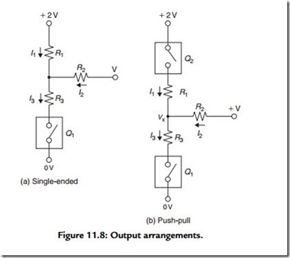
These two options are shown schematically in Figure 11.8, in which Q1 and Q2 are notional amplifier blocks, simplified to the extent that they are only considered as being
either open-circuit (O/C) or short-circuit (S/C), but with some internal resistance, shown as R3 [or R1 in the case of Figure 11.8(b)]. I have also adopted the convention that the current flow into the load resistor (R2) is deemed to be positive when the amplifier circuit is feeding current (as a current source) into the load and to be negative when the amplifier is acting as a current sink and drawing current from R2 and its associated power supply.
I have also labeled the voltage at the junction of these three resistors as Vx. The efficiency of the system can be considered as related to the extent of the change in the current through R2 brought about by the change from O/C to S/C in Q1 or Q2.
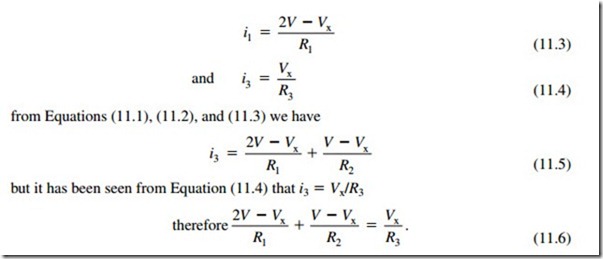
If we consider first the single-ended layout of Figure 11.8(a), when Q1 is O/C, the current flow into R2 is only through R1 and i2 = V/(R1 + R2). If, however, Q1 is short circuited, S/C, then, from inspection,
If we insert the actual values for R1, R2, and R3, we can discover the difference in output current flow in the load resistor (R2) between the O/C and S/C conditions of Q1. For example, if all resistors are 10 Ω in value, when Q1 is S/C, Vx will be equal to V, and there will be no current flow in R2 and the change on making Q1 O/C will be (V/20)A. If R1 and R2 are 10 Ω in value and R3 is 5 Ω, then the current flow in R2, when Q1 is O/C, will still be (V/20)A, whereas when Q1 is S/C, the current will be (–0.25 V/10)A and the change in current will be (3 V/40)A. By comparison, for the push–pull system of Figure 11.8(b), the change in current through R2, when this is 10 Ω and both R1 and R3 are 5 Ω in value, on the alteration in the conducting states of Q1 and Q2, will be (2 V/15)A, which is nearly twice as large.
The increase in available output power from similar output valves when operated at the same V+ line voltage in a push–pull rather than in a single-ended layout is the major advantage of this arrangement, although if the output devices have similar distortion characteristics, and the output transformer is well made, the even harmonic distortion components will tend to cancel. Also, the magnetization of the core of the output transformer due to the valve anode currents flowing in the two halves of the primary winding will be reduced substantially because the induced fields will be in opposition.
In addition, an increase in the drive voltage to the grids of the output valves, provided that it is not large enough to drive them into grid current, will, by reducing their equivalent series resistance (R1, R3 in the calculations given earlier), increase the available output power, whereas in the single-ended layout the dynamic drive current cannot be increased beyond twice the quiescent level without running into waveform clipping. However, there are other problems, which are discussed later.


