Output (Load-Matching) Transformer
This component is probably the most important factor in determining the quality of the sound given by a valve-operated audio amplifier, and the performance of this component is influenced by a number of factors, both mechanical and electrical, which will become of critical importance if an attempt is made to apply negative feedback (NFB) over the whole amplifier. However, for a low power system, such as might be used as a headphone amplifier, it is possible to make a quite decent sounding system without the need for
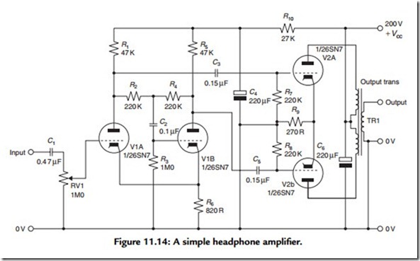
much in the way of exotic components, circuit complexity, or very high-quality output impedance-matching transformers, and I have sketched out in Figure 11.14 a typical circuit for a two-valve, 1W headphone amplifier based on a pair of 6SN7s or equivalents.
In this design the input pair of valves acts as a floating paraphase phase-splitter circuit, which provides the drive for the output valves. Since the cathode currents from the two input valves are substantially identical, but opposite in phase, it is unnecessary to provide a cathode bypass capacitor to avoid loss of stage gain. Also, since this cathode resistor is common to both valves, it assists in reducing any differences between the two output signals, as the arrangement acts, in part, as a long-tailed pair circuit such as that shown in Figure 11.12. Since the total harmonic distortion from a push–pull pair of triodes will probably be less than 0.5% and will decrease as the output power is reduced, provided a reasonable quality output transformer is used, I have not included any overall NFB, which avoids any likely instability problems. To match the output impedances of V2A and V2B to a notional load impedance of 100 Ω, a transformer turns ratio, from total primary to secondary, of 12:1 is required.
In more ambitious systems, in which NFB is used to improve the performance of the amplifier and reduce the distortion introduced by the output transformer, much more care is needed in the design of the circuit. In particular, the phase shifts in the signal that are introduced by the output transformer become very important if a voltage is to be derived from its output and fed back in antiphase to the input of the amplifier, in that to avoid instability the total phase angle within the feedback loop must not exceed 180° at any frequency at which the loop gain is greater than unity. This requirement can be met by both limiting the amount of NFB that is applied, which would, of course, limit its effectiveness, and controlling the gain/frequency characteristics of the system.
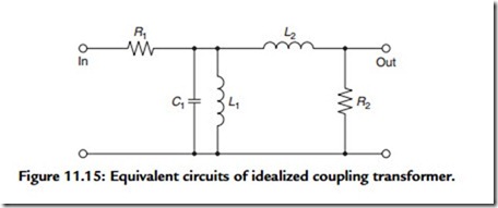
Although there are a number of factors that determine the phase shifts within the transformer, the two most important are the inductance of the primary winding and the leakage inductance between primary and secondary; a simple analysis of this problem, based on an idealized, loss-free transformer, can be made by reference to Figure 11.15. In this, R1 is the effective input resistance seen by the transformer, made up of the anode current resistance of the valve, in parallel with the effective load resistance, and L1 is the inductance of the transformer primary winding. When the signal frequency is lowered, a frequency will be reached at which there will be an attenuation of 3 dB and a phase shift of 60°. This will occur when R1 = jωL1, where ω is the frequency in radians per seconds.
R2 is the secondary load resistance, which is the sum of the resistance reflected through the transformer and the anode resistance, and L2 is the primary leakage inductance—a term that denotes the lack of total inductive coupling between primary and secondary windings—which behaves like an inductance between the output and the load and introduces an attenuation, and associated phase shift, at the HF end of the passband. The HF –3-dB gain point, at which the phase shift will be 60°, will occur at a frequency at which R2 = jωL2.
To see what these figures mean, consider the case of a 15-Ω resistive load, driven by a triode-connected KT66 that has an anode current resistance of 1000 ohms. Let us assume that, in order to achieve a low anode current distortion figure, it has been decided to provide an anode load of 5000 ohms. The turns ratio required will be V(5000/15) = 18.25:1 and the effective input resistance (R1) due to the output load reflected through the transformer will be 833 ohms. If it is decided that the transformer shall have an LF -3-dB point at 10 Hz, then the primary inductance would need to be 833/2π10 = 833/62.8 = 13.26 H. If it is also decided that the HF –3-dB point is to be 50 kHz, then the leakage inductance must be 833/2π50,000 = 2.7 mH. The interesting feature here is that if an output pentode is used, which has a much higher value of Ra than a triode, not only will a higher primary inductance be required, but the leakage inductance can also be higher for the same HF phase error.
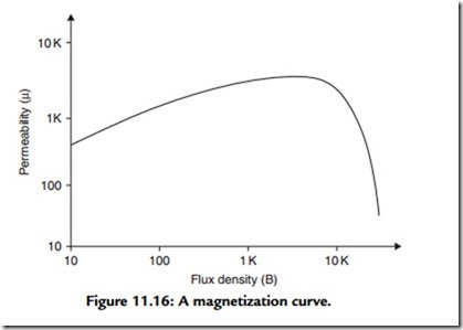
Unfortunately, a number of other factors affect the performance of the transformer. The first of these is the dependence of the permeability of the core material on the magnetizing flux density, as shown in Figure 11.16. Since the current through the windings in any audio application is continually changing, so therefore is the permeability, and with it the winding inductances and the phase errors introduced into the feedback loop. Williamson
urged that, for good LF stability, the value of permeability, μ, for low values of B should be used for primary inductance calculations.
Second, this change in inductance, as a function of current in the windings, is a source of transformer waveform distortion, as are—especially at high frequencies—the magnetic hysteresis of the core material and the eddy current losses in the core. These problems are exacerbated by the inevitable DC resistance of the windings and provide another reason, in addition to that of improved efficiency, for keeping the winding resistance as low as possible.
The third problem is that the permeability of the core material falls dramatically, as seen in Figure 11.16, if the magnetization force exceeds some effective core saturation level. This means that the cross-sectional area of the core (and the size and weight of the transformer) must be adequate if a distortion-generating collapse in the transformer output voltage is not to occur at high signal levels. The calculations here are essentially the same as those made to determine the minimum turns per volt figure permissible for the windings of a power transformer.1
In practical terms, the requirements of high primary inductance and low leakage inductance are conflicting and require that primary winding is divided into a number of sections between which portions of the secondary winding are interleaved. Williamson proposed that eight secondary segments should be placed in the gaps left between 10 primary windings. This increases the stray capacitance, C1, across the primary winding and between primary and secondary coils. However, the HF phase errors introduced by these will probably be unimportant within the design frequency spectrum.


