Effect of Output Load Impedance
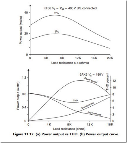
This is yet another area in which there is a conflict in design requirements, between output power and output stage distortion. Figure 11.17(a), shows the output power
given for 1 and 2% THD values by a push–pull pair of U/L-connected KT88s in relation to the anode to anode load impedance chosen by the designer. These data are courtesy of the GEC2 Since the distortion can also alter in its form as a function of load impedance, Figure 11.17(b) shows the way these circuit characteristics change as the load resistance changes. The figures given for a single-ended 6AK6 output pentode are due to Langford-Smith.
Related posts:
Solenoid and motor operated valves:Solenoid Valves
Engine Valve System part6
bipolar Transistors:Basic Transistor operation
DC Motors
VARIABLE-SPEED DRIVES:AC POWER FACTOR
How to locate, test, and repair part2
Troubleshooting variable speed drives:Power electronic components
Fuel System – Carburetor Service (part3)
Feedback Control Theory:Frequency Response
Valve (Tube-Based) Amplifiers:Available Output Power
Troubleshooting AC motors and starters:Measurements used for a motor
Testing of d.c.Machines:Field’s Test for Series Motor
CLASSIFICATION OF DC MACHINES part1
TRANSFORMER COMPONENTS AND MAINTENANCE:INTERCONNECTION WITH THE GRID
