Test Procedure Example 2
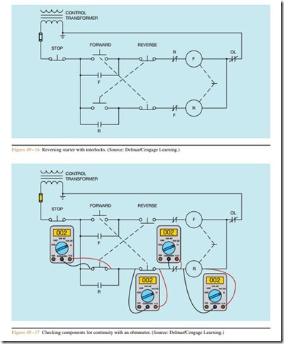
The circuit shown in Figure 49 – 16 is a reversing starter with electrical and mechanical interlocks. Note that double acting push buttons are used to disconnect one contactor if the start button for the other contactor is pressed. Now assume that if the motor is operating in the forward direction, and the REVERSE pushbutton is pressed, the forward contactor de-energizes but the re- verse contactor does not. If the FORWARD push button is pressed, the motor will restart in the forward direction.
To begin troubleshooting this problem, make mental notes of problems that could cause this condition:
1. The reverse contactor coil is defective.
2. The normally closed F auxiliary contact is open.
3. The normally closed side of the FORWARD push button is open.
4. The normally open side of the REVERSE push but- ton does not complete a circuit when pressed.
5. The mechanical linkage between the forward and reversing contactors is defective.
Also make mental notes of conditions that could not
cause the problem:
1. The STOP button is open. (If the STOP button were open, the motor would not run in the forward direction.)
2. The overload contact is open. (Again, if this were true, the motor would not run in the forward direc- tion.)
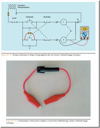
To begin checking this circuit, an ohmmeter can be used to determine if a complete circuit path exists through certain components. When using an ohmme- ter, make certain that the power is disconnected from the circuit. A good way to do this in most con- trol circuits is to remove the control transformer fuse. The ohmmeter can be used to check the continuity of the reverse contactor coil, the normally closed F con- tact, the normally closed section of the FORWARD push-button, and across the normally open REVERSE push-button when it is pressed (Figure 49 – 17).
The ohmmeter can be used to test the starter coil for a complete circuit to determine if the winding has been burned open, but it is generally not possible to determine in this way if the coil is shorted. To make a final determination, it is generally necessary to apply power to the circuit and check for voltage across the coil. Since the REVERSE push button must be closed to make this measurement, it is common practice to connect a fused jumper across the push button if there is no one to hold the button closed (Figure 49 – 18). A fused jumper is shown in Figure 49 – 19. When using a
fused jumper, power should be disconnected when the jumper is connected across the component. After the jumper is in position, power can be restored to the circuit. If voltage appears across the coil, it is an indication that the coil is defective and should be replaced or that the mechanical interlock between the forward and reverse contactors is defective.

