Gate-commutated inverters (DC/AC converters)
Most modern AC VSDs in the 1–500 kW range are based on Gate-commutated devices such as the GTO, MOSFET, BJT, and IGBT, which can be turned ON and OFF by low- power control circuits connected to their control gates.
Operating principle An inverter works on a DC supply giving a variable frequency AC output. It can be operated either as a step wave inverter or a PWM inverter.
In a step wave inverter, the transistors are switched such that the phase difference is 60º and each transistor is kept on for 180º. To vary the output AC waveform frequency, the duration between the turn on of transistors is changed. The output of AC voltage is varied by changing the DC input voltage. This type of an inverter has problems of a pulsating torque due to harmonics in the output voltage. This gives a pulsating motion of the rotor at low speeds.
The pulsating torque can be eliminated by the use of pulse width modulation (PWM) type inverters since their output has low harmonic content. The details of this type of inverter are explained later in this chapter. With a DC supply and semiconductor power electronic switches, it is not possible to obtain a pure sinusoidal voltage at the load. On the other hand, it may be possible to generate a near-sinusoidal current. Consequently, the objective is that the current through the inductive circuit should approximate a sinusoidal current as closely as possible.
Single-phase square wave inverter
To establish the principles of gate-controlled inverter circuits, Figure 6.21 shows four semiconductor power switches feeding an inductive load from a single-phase supply.
This circuit can be considered as an electronic reversing switch, which allows the input DC voltage VD to be connected to the inductive load in any one of the following ways:
1. S1 = on, S4 = on…. giving + VD at the load
2. S2 = on, S3 = on…. giving – VD at the load
3. S1 = on, S2 = on…. giving zero volts at the load
4. S3 = on, S4 = on…. giving zero volts at the load
5. S1 = on, S3 = on…. giving a short-circuit fault
6. S2 = on, S4 = on…. giving a short-circuit fault.
However, these four switches can be controlled to give a square waveform across the inductive load, as shown in Figure 6.20. This makes use of the switch configurations
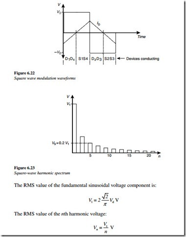
(1) and (2), but not the switch configuration (3) or (4). Clearly, for a continued safe operation, option (4) should always be avoided. In the case of a purely inductive load, the current waveform is a triangular waveform, as shown in Figure 6.22. In the first part of the cycle, the current is negative although only switches S1 and S4 are on. Since most power electronic devices cannot conduct negatively, to avoid damage to the switches, this negative current would have to be diverted around them.
Consequently, diodes are usually provided, anti-parallel with the switches to allow the current flow to continue. These diodes are sometimes called reactive or freewheeling diodes. These diodes conduct when the voltage and current polarities are opposite. This occurs when there is a reverse power flow back to the DC supply.
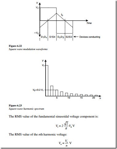
The frequency of the periodic square wave output is called the fundamental frequency. Using Fourier analysis, any repetitive waveform can be resolved into a number of sinusoidal waveforms. Each comprises one sinusoid at a fundamental frequency and a number of sinusoidal harmonics at higher frequencies, which are multiples of the fundamental frequency. The harmonic spectrum for a single-phase square wave output is shown in Figure 6.23. With an increase in frequency, the amplitude of the higher-order harmonics voltages fall off rapidly.
This illustrates that the square wave output voltage, has many unwanted components of reasonably large magnitude at frequencies close to the fundamental. The current flow in the load is due to an output voltage distortion, as demonstrated by the non-sinusoidal current wave-shape. In this example, the current has a triangular shape.
If the square-wave voltage were presented to a single-phase induction motor, the motor would run at the frequency of the square-wave. Being a linear device (inductive/resistive load), however, it would draw non-sinusoidal currents and would suffer additional heating due to the harmonic currents. These currents may also produce pulsating torques.
To change the speed of the motor, the fundamental frequency of the inverter output can be changed by adjusting the switching speed. To increase frequency, the switching speed can be increased, and to decrease frequency, the switching speed can be decreased.
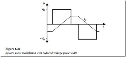
The output voltage magnitude can also be controlled. The average inverter output voltage can be reduced by inserting periods of zero voltage, using a switch configuration (3). Each half cycle then consists of a square pulse, which is only a portion of a half period, as shown in Figure 6.24.
The process of changing the width of the pulse, to reduce the average RMS value of a waveform is called PWM. In the single-phase example in Figure 6.24, PWM makes it possible to control the RMS value of the output voltage. The fundamental sinusoidal voltage component is continuously variable in the following range:
The harmonic spectrum of this modified waveform depends on the fraction, that the pulse is, of the full square wave, but is broadly similar to the waveform shown earlier.


