Troubleshooting strategies
Strategies for troubleshooting of control circuits and ‘Ladder Logic Circuits’:
1. It is important to have the control circuit drawings, details of devices, their interconnection and interlocking while troubleshooting the control circuits. To troubleshoot a machine or equipment problem, it is good to have the ‘Manufacturer’s Operation and Maintenance Manual’, as well as the ‘Troubleshooting Instructions’.
2. ‘Block Interlocking Diagram’ and ‘Control Sequences’ of the equipment/ machine operations should be available during troubleshooting.
3. Drawings and details of the power circuit of the equipment or the machine,
control devices, contactors, timers, counters, safety, and protection devices, etc. are needed for troubleshooting the root cause.
4. Appropriate test and measurement instruments required for testing the control and power circuit of the equipment, or the machine must be available.
5. Switch OFF the main power supply to the equipment/machine and switch control supply ON, to avoid any mishaps or accidents while troubleshooting control circuits because of the sudden starting of the equipment.
6. As control circuits are different from equipment-to-equipment and machine- to-machine, it is not be possible to formulate a single or common strategy for
troubleshooting control circuits. However, exemplary/standard engineering and trade practices must be followed while troubleshooting the control
circuits.
General document checklist for troubleshooting
./ Control circuit drawings
./ Manufacturers operations and maintenance manuals and troubleshooting instructions
./ Block interlocking diagram and control sequences involving the equipment/
machine
./ Drawings and details of power circuits of the equipment/machine
./ Details of devices, control devices, contactors, timers, counters, safety/protection
./ Power circuit of the equipment or the machine.
The sequence is as listed below:
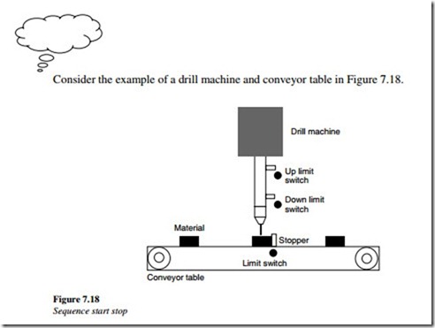
1. The conveyor table should run as long as material strikes the conveyor limit switch that is provided.
2. The ‘Stopper and Drill’ should go up and down until it strikes the ‘Down’ limit switch. This makes a hole in the stationary material for 1 s. Again, the ‘Drill’ should go up until it strikes the ‘Up’ limit switch.
3. Then the conveyor starts again until the next material strikes the conveyor limit switch.
4. Outputs from PLC can be configured for conveyor start/stop, drill machine
start/stop, drill up/down and stopper up/down.
5. Inputs to the PLC are the conveyor limit switch and drill machine up/down limit switch, conveyor table on/off.
7.14 Ladder logic design exercise
Prepare a ‘PLC Ladder Logic Control Circuit’ from the above example.
