Motor testing
Advances in a number of technological fields have contributed greatly to the development of testing equipment. This has made the maintenance of electric motors a more precise science.
The task of keeping all ‘systems on the go’ is now the responsibility of a ‘cut to the bone’ staff of technicians and engineers.
Despite all the hi-technology, the proper maintenance of equipment like motors is dependent on training, motivation, and awareness of the man behind the machine. The following tools and equipment are now available for monitoring, measuring, and metering the various parameters of the motors in a motor performance/operation.
Different tests provide various data, related to the motor, which give an idea about the probable performance of the motor and its efficiency.
Methods of testing DC machines
DC motors are tested by using the following methods:
1. Direct loading or brake test
This test is meant for calculating the efficiency of a motor and is a direct loading test. It is used for small motors only. The motor is loaded directly by a mechanical rope or a belt brake.
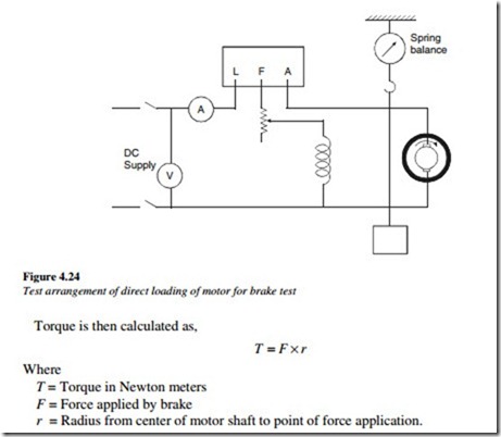
A typical arrangement for the direct loading of the motor for a brake test is shown in Figure 4.24.
In this method, a force is applied by adjusting the brake and is measured in Newtons using an attached spring balance.
A voltmeter and an ammeter are connected for measuring the supply voltage and the current taken by the motor.
A load is applied gradually to the motor and the corresponding current, voltage, torque, and speed-reading are noted. In the case of testing a series motor, it is better to take the readings from a high load to gradually reducing load.
As the whole output is wasted in heat, it is used only for small capacity motors.
A measurement of force, exerted by the arm and the radius or length of the arm, can give the torque.
If R is the radius of the pulley, and W and w are weights on either side of the brake arrangement, then
The efficiency of the motor:
A dynamometer arrangement can be used alternatively to measure the pull and the torque on the motor under braking conditions.
2. Swinburne test
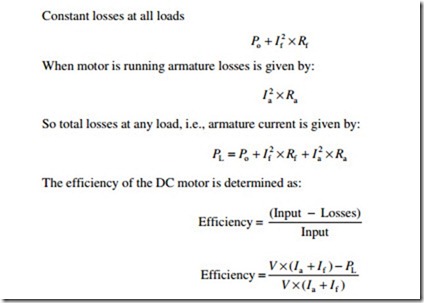
This test is for shunt and compound type of DC machines and gives the efficiency of the motor on any load, from the data calculated on ‘no load’ conditions.
This is an indirect method of testing the efficiency of a DC shunt motor, by measuring losses, like iron loss and mechanical losses. In addition, it is assumed that these losses remain constant during all load conditions.
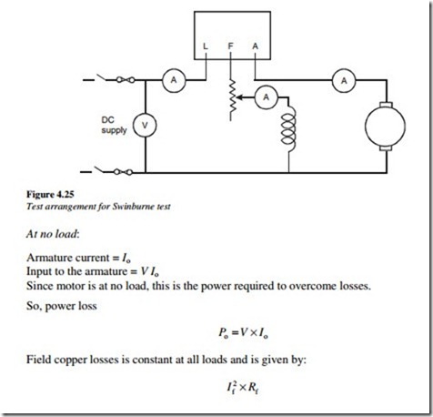
The DC motor is run on ‘no load’. The voltage and speed are adjusted to the rated values. A connection diagram for the Swimburne test is shown in Figure 4.25.
The armature resistance (Ra) is measured with an ammeter/voltmeter method, including all of the series and interpole winding. Similarly, the shunt field resistance (Rf) is also measured.
The motor is run at a rated speed and at a rated voltage without any load.
The following are the advantages of the Swinburne test:
• The efficiency of the machine can be determined without any direct loading.
Energy is saved during the testing. This is quite useful, particularly for large machines.
• The efficiency can be determined at any load.
The following are the disadvantages of the Swinburne test:
• Only shunt and compound machines can be tested by this method. The series machines cannot be tested as they cannot run on no load.
• The effect of commmutation and armature reaction is not considered or tested in this method. The errors due to assumption of constant iron losses at all the loads are insignificant.
3. Hopkinson test on shunt motors
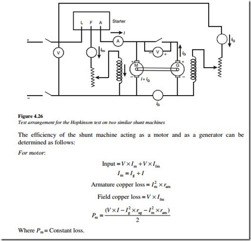
The direct loading method for large machines involves huge power losses. To avoid this, the regenerative method of testing is used. This test can be performed on two identical shunt machines, mechanically coupled to each other. One machine is run as the motor and the other as a generator. A typical arrangement for the Hopkinson test on two similar shunt machines is shown in Figure 4.26.
One machine starts as a motor taking supply from the mains. The field current is adjusted to run the machine at the rated speed. The second machine is mechanically coupled and is run at the same speed. The excitation of the machine is so adjusted, that the voltage across the armature is slightly higher than the supply voltage. This is checked with a Voltmeter V. The polarities of the machines should be suitable for a parallel operation. When the voltmeter reads zero or a slightly higher 1 or 2 V indicating that it would be generator action, the switch is closed so that both the machines are in parallel across the supply. As both the machines are similar and equal in size and rating, the constant losses – friction, windage, and iron – are assumed to be equal.
4. Retardation test
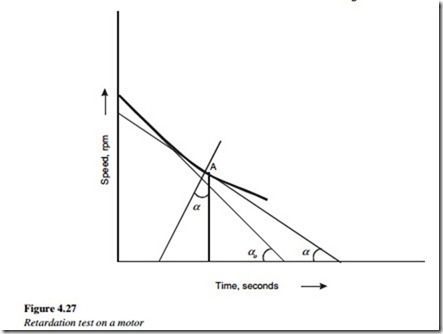
If a motor is brought up to the speed and then switched off, it will slow down typically, as shown in Figure 4.27.
The angular retardation dowdy at any instant is directly proportional to the rotating
torque and it varies inversely as the moment of inertia (J) of the motor. The power consumed in overcoming the losses due to rotation is given as follows:
The test can be carried out on a separately excited motor or shunt motor. The friction losses and iron or core losses can be determined by this test.
5. Field’s series test
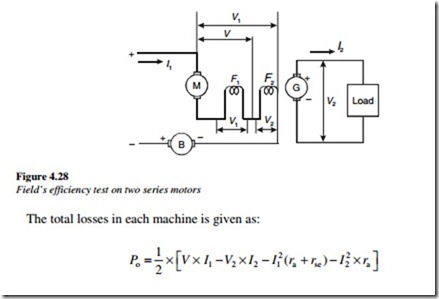
This test is used for obtaining the efficiency of two similar motors. This test avoids the difficulty of obtaining readings on light loads, by using the motor current to excite the field as a generator. The generator armature is connected to the load resistance. The connection diagram for Field’s test is shown in Figure 4.28. As both the machines have the same excitation, iron losses in both machines are considered equal.
